Ursachen für das Versagen von Schachtförderseilen: Ermüdung, Verschleiß, Korrosion und Lastumverteilung
Why mine-hoist wire ropes fail: fatigue, wear, corrosion, load redistribution, inspection limits, and the standards that guide safe decisions.
A mine-hoist wire rope is not a solid steel bar. It is a moving assembly of helically laid wires and strands. During each winding cycle, those elements carry changing tension, bend over sheaves or onto drums, twist, press against adjacent wires and undergo small relative movements. The result is a distributed mechanical system in which damage may begin at a surface, an internal contact, a corrosion pit or a local defect before it becomes visible at rope scale.
The final fracture therefore does not necessarily identify the initiating cause. Progressive wear, fatigue, corrosion or earlier wire breaks can reduce effective load-bearing capacity. Full-rope experiments further show that wear and broken wires can redistribute load so that surviving wires may ultimately fail by ductile overload. Conversely, a severe one-time overload, attachment failure or material nonconformity can produce a different history. Understanding mine hoist wire rope failure therefore requires distinguishing the initiating degradation mechanism from damage propagation, loss of effective section and the final fracture mode. (Schrems, 1994; Chang et al., 2019; Zhang et al., 2017; Singh, Mallick and Verma, 2016)
How the evidence was reviewed
Bei diesem Artikel handelt es sich um einen forschungsbasierten, ingenieurwissenschaftlichen narrativen Übersichtsartikel und nicht um eine systematische Übersichtsarbeit, Metaanalyse oder erschöpfende Literaturstudie. Gezielte Recherchen wurden über Zeitschriftenverlage und DOI-Einträge zu den Themen Fördermaschinendynamik, Drahtseil-Reibkorrosion, Biegewechselfestigkeit, Verschleiß, Korrosionsermüdung, Torsion, Lastumverteilung bei Drahtbrüchen, Schadensanalysen, elektromagnetische Prüfungen und Restfestigkeitsprüfungen durchgeführt. Recherchen und Normenprüfungen wurden am 3. September 2026 abgeschlossen. Priorität erhielten originale begutachtete Studien (Peer-Review), bergbauspezifische Nachweise, Versuche an Seilen in Originalgröße und Betriebsausfälle; Tests an Einzeltiteln und Litzen wurden nur für mechanismenbezogene Schlussfolgerungen berücksichtigt. Offizielle ISO- und BSI-Katalogeinträge, der aktuelle eCFR-Text, MSHA-Materialien, Leitlinien der britischen HSE sowie der im April 2026 zugelassene NSW-Code wurden separat überprüft.
Repräsentative Suchkombinationen umfassten “Fördermaschinenseil”, “Ermüdung von Schachtförderseilen”, “Drahtseilreibverschleiß”, “Korrosionsermüdung von Förderseilen”, “Biegeermüdung von Drahtseilen”, “ZfP von Koepe-Seilen”, “Lastumverteilung bei Drahtbrüchen”, “Seilprüfung in Schachtanlagen” sowie “Schadensanalyse von Förderseilen”. Studien wurden berücksichtigt, wenn sie direkt zur Dynamik von Förderschachtanlagen, Seil- oder Drahtschadensmechanismen, Schadensuntersuchungen, der Prüfung oder der Interpretation der Restfestigkeit beitrugen. Allgemeine Studien zu Drahtseilen wurden nachrangig behandelt, es sei denn, es lagen keine bergwerksspezifischen Nachweise vor oder eine Klärung der Mechanismen war erforderlich. Literaturverzeichnisse und Zitationsketten relevanter Primärarbeiten wurden selektiv überprüft, um weitere Originalstudien zu ermitteln.
Im Text werden Evidenztypen identifiziert, weil ein Modell, ein Drahtprüfungstest, ein beschleunigter Vollseilversuch, ein forensischer Fall und ein rechtlicher Schwellenwert unterschiedliche Fragen beantworten. Widersprüchliche Ergebnisse wurden im Hinblick auf Testmaßstab, Belastung, Umgebung und die Frage interpretiert, ob eine Studie die Rissinitiierung oder die Rissausbreitung gemessen hat. Mehrere zitierte experimentelle Arbeiten stammen von sich überschneidenden Forschungsgruppen der China University of Mining and Technology; sie bilden ein kohärentes Forschungsprogramm und keine mehreren unabhängigen Reproduktionen. Unabhängige forensische, feldüberwachte und ausgemusterte Seilnachweise aus den Vereinigten Staaten, Indien, der Türkei, Polen und der Slovakia erweitern diese Einschränkung, heben sie jedoch nicht auf.
A mine winding rope experiences a load history, not one static load
Die nominelle Hängelast beschreibt nicht die vollständige Beanspruchung, der ein Bergwerksförderseil ausgesetzt ist. Beschleunigung, Verzögerung, Schwingung, sich verändernde Hängeseillänge, Biegung, Torsion und Betriebsausgleichsvorgänge verändern sowohl die Systemspannung als auch die örtlichen Bedingungen an den Drahtkontaktstellen.
Die Systemmodellierung von Wang, Zhang und Ge veranschaulicht den Unterschied zwischen globalen und lokalen Maßstäben. Für ein bestimmtes Modell einer Förderanlage in einem Kohlebergwerk berechneten die Autoren dynamische Seilspannungen im Bereich von 0 bis 30,9 kN. Anschließend leiteten sie ausgewählte Kontaktkräfte zwischen den Drahtseilen von 38,3, 60,5, 102,7 und 378 N sowie relative Verschiebungen von 62,5 und 113,2 μm an bestimmten Kontaktstellen ab. Dabei handelte es sich um aus Simulationen abgeleitete Eingangsgrößen für nachfolgende Drahtversuche – nicht um Feldmessungen, keine Auslegungslasten und keine auf andere Schächte übertragbaren Grenzwerte. Ihr Wert ist konzeptioneller Natur: Großräumige Bewegungen des Förderaufzugs können interne Verschiebungen mit geringer Amplitude erzeugen, die zu Reibungsverschleißschäden führen können. (Wang, Zhang und Ge, 2013; Wang et al., 2012)
Die Schachttiefe ist von Bedeutung, da ein längeres aufgehängtes Seil ein Eigengewicht hinzufügt und das dynamische Verhalten des Systems verändert. Die Tiefe allein führt nicht zum Versagen; sie wirkt zusammen mit Seilmasse, Nutzlast, Geschwindigkeitsverlauf, Fördermaschinenart, Geometrie und Beanspruchung. Die Verwendung von längenabhängigen Formeln für die Mindestfestigkeit in Bergbauvorschriften spiegelt dieses sich verändernde Auslegungsproblem wider, jedoch ist eine gesetzliche Formel für den Sicherheitsfaktor keine Vorhersage der Versagenswahrscheinlichkeit für ein bestimmtes Seil.
Das Unterschreiten einer nominellen Nutzlastgrenze hebt daher die zyklische Schädigung nicht auf. Der Zustand hängt vom Lastkollektiv und dem Seil-Fördermaschinen-System ab, nicht nur von der größten statischen Last.
Bending and internal contact create repeated local damage
Ein Seil muss sich über eine Seilscheibe oder beim Einlaufen in eine Trommel biegen. Diese wiederholte Krümmung erzeugt eine primäre Biegung des Seils sowie sekundäre Biege- und Kontaktspannungen auf Drahtebene. Benachbarte Drähte und Litzen drücken und bewegen sich zudem gegeneinander. Diese Mechanismen können gleichzeitig auftreten, weshalb “Ermüdung” nicht als einheitlicher Prozess betrachtet werden sollte.
In einem von Zhang und Kollegen durchgeführten beschleunigten Vollseil-Versuch wurden Seile mit 6×19-Faserkern wiederholt über Stahl- und modifizierte Nylonrollen gebogen. In diesem Versuchsaufbau erreichte das mit der modifizierten Nylonrolle verwendete Seil mehr als das Doppelte der angegebenen Biegeermüdungslebensdauer des mit der Stahlrolle verwendeten Seils. Die Studie zeigt, dass das Material der Umlenkrolle und das Kontaktverhalten die Schadensentwicklung beeinflussen können. Sie liefert jedoch keinen allgemeingültigen Lebensdauer-Multiplikator: Seilaufbau, Durchmesser und Rille der Umlenkrolle, Belastung, Geschwindigkeit, Umgebungsbedingungen sowie die begrenzte Testpopulation des Experiments schränken die Übertragbarkeit ein. (Zhang et al., 2013)
Nor does the result prove that synthetic sheaves are inherently safer. ISO 4309:2017, which covers crane, winch and hoist ropes rather than serving as the default mine-shaft rope standard, warns that systems using exclusively synthetic sheaves or synthetic linings with single-layer drum spooling can accumulate internal wire breaks before adequate external evidence appears. The defensible lesson is that the rope and sheave form an interacting contact system: changing material or geometry can change both the damage rate and where damage becomes detectable. (ISO 4309:2017)
Fretting: lower friction or slip does not necessarily mean less damage
Fretting is surface damage caused by small, repeated relative motion under contact load. In a rope it can occur between individual wires or between strands. Fretting wear removes material; fretting fatigue describes crack initiation and growth promoted by that cyclic contact. Fretting corrosion additionally involves chemical or electrochemical surface reactions. These terms are related but not interchangeable.
In a forensic examination of a non-rotating skip-hoist rope from an underground mine, Schrems found failures associated with interstrand wear and fatigue. Fractography also showed why the most obvious wear scar need not coincide with the exact crack origin: cracks may begin where the local multiaxial stress state is most damaging, including a less visually dramatic location. This is one service failure, not evidence of population-wide frequency, but it is direct mine-rope evidence that visible metal loss alone can be an incomplete root-cause indicator. (Schrems, 1994)
Controlled multi-wire experiments by Peng and colleagues used a seven-wire helical assembly—six 1 mm outer wires around a 1.1 mm core—under dry laboratory conditions. As lateral load increased from 80 to 320 N, the reported steady coefficient of friction fell from about 0.73 to 0.66, while maximum wear depth increased from 10.9 to 23.1 μm and average wear width from 111.5 to 135.8 μm. These are reported results for the study's wire geometry, tension, fretting amplitude and environment; they are not mine-rope service limits. The experiment supports a narrower conclusion: lower measured friction can coexist with greater wear because normal load, contact stress and dissipated energy also change. (Peng et al., 2023)
Other multi-wire tests from the same wider research lineage show that frequency, wire tension and helical-contact geometry can change friction and wear. These studies improve mechanism understanding but should not be counted as independent field replication, and their test rigs do not reproduce every contact in a full rope. (Huang et al., 2025)
The correct conclusion is not that lower friction causes more damage. It is that friction coefficient or relative slip alone cannot represent rope health. Contact pressure, stress distribution, debris, lubrication, evolving scar geometry and the transition among adhesion, partial-slip and gross-slip regimes also matter.
External wear removes metal and can shorten later fatigue life
External wear at a sheave, groove or multilayer-drum crossover is not merely cosmetic. It reduces metallic area, changes local geometry, concentrates stress and disturbs load sharing. Diameter reduction, loss of metallic area and residual breaking force are related condition indicators, but they are not equivalent measurements.
Chang and colleagues conducted an accelerated full-rope study on a 9.3 mm 6×19 fibre-core transmission rope whose initial measured breaking force was 52.5 kN. Under the most severe rope–sheave wear sequence reported, breaking force declined from approximately 48 to 23 kN and subsequent bending-fatigue endurance from about 6,200 to 200 cycles. These values describe test endpoints in one small-rope rig using a Q235 sheave. They are not expected mine-shaft service lives, uncertainty bounds or discard criteria; the paper does not establish that the same percentage loss occurs in a full-size mine winding rope. (Chang et al., 2025)
In the same research programme, a rope–rope wear sequence reduced breaking force from about 50 to 46 kN, a smaller change than in that study's rope–sheave sequence. It would be unsound to generalize that rope–sheave wear is always more severe: the rigs represented different contacts and used different loads, speeds and contact lengths. The comparison is conditional on the experimental arrangements.
Controlled-wear and finite-element work has further shown that groove-shaped or irregular scars can produce non-uniform stress and load sharing. Yet the Schrems service failure showed that the deepest visible loss does not invariably locate the fatigue origin. Average diameter can therefore miss a deep local scar, an unfavourable scar orientation, clustered breaks or internal damage. (Chang et al., 2019; Schrems, 1994)
Lubrication changes the contact regime; it does not eliminate fatigue
Suitable lubrication can reduce friction and wear and can contribute to corrosion protection under appropriate conditions. In Peng and colleagues' seven-wire test system, the steady coefficient of friction was about 0.16–0.22 with the tested oil versus roughly 0.58–0.75 under dry conditions. Reported dry wear widths were approximately 160–240 μm, compared with about 40–120 μm in lubricated tests. The observed mechanisms also changed: dry contacts showed abrasive, adhesive and fatigue wear, while lubricated contacts were dominated more by abrasive and fatigue processes. (Peng et al., 2023)
That result demonstrates a protective effect under the tested conditions, not a universal lubricant specification or relubrication interval. It used one laboratory lubricant and a small multi-wire assembly, not an operating mine rope. Lubricant chemistry, viscosity, application method, contamination and compatibility with the rope core and surface finish all affect performance.
Friction-winding or Koepe systems introduce an additional constraint: traction between rope and the drive sheave or drum is part of the system design. UK HSE guidance states that externally applied lubricants or dressings on friction-winder ropes must not significantly reduce the coefficient of friction between the rope and driving drum and warns against over-lubrication because it can cause rope slip or uneven travel. More lubricant is therefore not automatically safer, and an unsuitable dressing may conflict with traction requirements. (HSE) UK HSE shaft-rope guidance also notes that external lubricant can restrict the penetration of dirt and grit that would otherwise increase abrasion, while excessive use of a sticky lubricant can attract grit and reduce rope life. This is general shaft-rope guidance, not a finding of the Peng experiment. Rope and winder manufacturers' instructions, the approved winding-system design and the governing mine rules should control the specification and application practice. (HSE)
Forensic analysis of two ropes used in underground coal mines reported poor lubrication together with wear and corrosion. This supports inadequate lubrication as a contributing condition in those cases, not as a sole cause or the dominant cause across mines. (Singh, Mallick and Verma, 2016)
ISO 3156:1976 addresses characteristics and tests for impregnating compounds, lubricants and service dressings used with stranded mine-hoisting ropes. It is a materials-and-test standard; it does not provide one field relubrication interval for every shaft.
Corrosion and fatigue interact; pH alone does not predict rope life
Corrosion may remove metal, create pits and disrupt protective surface conditions. Under cyclic loading, pits and other surface defects can concentrate stress and become crack-initiation sites. Corrosion fatigue is therefore a coupled process: the environment changes the surface from which mechanical cracking may begin, while cyclic deformation and contact repeatedly disturb that surface.
Wang and colleagues tested smooth 1 mm wires taken from a 6×19 mine rope. The wire had a reported ultimate tensile strength of 1,750 MPa and was tested in laboratory solutions with pH values of 2.97, 6.97 and 9.97. The acidic solution produced the shortest fatigue lives among the conditions examined. This wire-level result supports the effect of that solution chemistry on crack initiation; it does not show that acid mine water alone causes full-rope failure or that pH is a sufficient environmental descriptor. (Wang et al., 2016)
The same study shows why fatigue-cycle figures require restraint. At a maximum stress of 800 MPa in the neutral solution, the study reported approximately 72,000 cycles at 2 Hz and stress ratio R = 0.5, versus about 5,700 cycles at 5 Hz and R = 0.05. These were test results for smooth 1 mm wires in specified solutions—not a service-life range for mine ropes. Fatigue endurance also commonly exhibits scatter, and the article did not report these two values as universal population means.
Results from other corrosion-fatigue studies may appear to conflict when they measure different stages. Smooth-wire tests include crack initiation; pre-cracked specimens emphasize propagation. Frequency changes exposure time per cycle, stress ratio changes mean stress and crack closure, and solution chemistry involves more than pH. A trend observed for initiation cannot automatically be applied to crack growth in a full rope.
Crossed-wire tension–torsion fretting-corrosion experiments add another complication. In one study, mechanical indicators such as dissipated energy, wear depth and crack-propagation measures increased under certain loading changes while the electrochemical-corrosion response moved in the opposite direction. Mechanical wear and electrochemical reaction are distinct damage channels; intensifying one need not increase the other. This was a crossed-wire laboratory study, not a field rope. (Wang, Zhu and Song, 2020)
The defensible engineering conclusion is conditional: corrosion-fatigue response depends on solution chemistry, exposure time, stress amplitude and ratio, frequency, rope construction, lubrication and pre-existing damage.
Torsion, installation and material conformity add different risks
Residual or imposed torsion
Torsion changes how helically arranged wires and strands press, slide and bend against one another. In accelerated full-rope bending tests, Hu and colleagues imposed twisting and untwisting and reported an approximately linear reduction in bending-fatigue endurance across their tested angular range. Both directions increased elongation, while twisting was more damaging than untwisting in that configuration. (Hu et al., 2023)
That ordering is not universal. Laboratory-imposed torsion is not identical to every installation error or source of service rotation, and the response depends on rope construction, lay direction, load and rig geometry. The supported conclusion is that residual or imposed torsion can alter internal contact, wear-scar development and bending-fatigue endurance. Installation and rope replacement should therefore control twist in accordance with the rope and winder documentation.
Material and manufacturing conformity
Premature damage can also result when the supplied rope does not match its declared material or construction. Peterka and colleagues examined a prematurely damaged drilling-hoist rope and an unused reserve sample. Their forensic and metallurgical analysis found that the rope was manufactured in a grade different from the declared 1,770 MPa class. Mixed-strength wires in the outer strand layer deformed differently; lower-strength wires released, rolled and fractured after short service. (Peterka et al., 2014)
This is a single drilling-hoist case, not evidence that manufacturing nonconformity is a common mine-shaft failure cause. It does show why procurement needs more than a nominal breaking-force entry: rope construction, grade, lay, coating, core, lubrication, test certificates and acceptance evidence must match the approved duty.
ISO 3154:1988 specifies technical delivery requirements for stranded mine-hoisting ropes within its scope; ISO 5614:1988 performs a comparable role for locked-coil mine-hoisting ropes. EN 12385-6 provides particular requirements for stranded mine-shaft ropes within the EN 12385 framework, while EN 12385-7 specifies additional requirements for full-locked-coil hoist ropes and half- or full-locked-coil guide ropes for mine shafts. Conformity at delivery is necessary, but it does not establish in-service condition after installation.
Broken wires change the load path before final rupture
A broken wire is not only a count. Once it stops carrying its intended share, forces and stresses redistribute through the remaining structure. Damage location and clustering can therefore matter as much as the total number of breaks.
Zhang and colleagues introduced controlled surface-wire break patterns into full ropes and subjected them to repeated bending. The tests and associated analysis showed increased inner-strand stresses and contact forces after surface breaks. Among the configurations tested, a concentrated 1×4 pattern produced the most severe response. This does not make four adjacent breaks a universal discard threshold: the defects were manufactured in one rope construction, and legal criteria depend on rope type, reference length and jurisdiction. The study supports the mechanism-level conclusion that concentrated damage can be more consequential than the same number of separated breaks. (Zhang et al., 2017)
In derselben Studie wurden Verschleiß-/Ermüdungsbrüche von duktiler Überlastung bei Drähten unterschieden, die bis zum endgültigen Versagen durchhielten. Kontrollierte Verschleißversuche haben einen vergleichbaren Ablauf gezeigt, bei dem stark abgenutzte äußere Drähte zuerst versagten und innere Drähte anschließend veränderte Lasten trugen. Aus diesem Grund beweist eine duktile Überlastung der zuletzt verbliebenen Drähte nicht automatisch, dass eine übermäßige Nutzlast das Ereignis ausgelöst hat. Es kann sich um den endgültigen Bruchmodus handeln, nachdem fortschreitende Schäden den wirksamen Querschnitt verringert haben. (Chang et al., 2019)
Diese Abfolge ist nicht zwingend. Eine einmalige Überlastung, ein Versagen der Befestigung, ein Schockereignis oder ein Materialfehler können eine andere Kette auslösen. Die Beweislage spricht bei Schadensuntersuchungen stark dafür, den auslösenden Degradationsmechanismus von der finalen Bruchform zu unterscheiden.
Mine-hoist rope inspection: appearance, age and nominal capacity cannot establish complete condition
Eine visuelle Prüfung ist unverzichtbar, jedoch kann die Oberfläche nicht jeden inneren Defekt offenbaren. Die Durchmessermessung kann bestimmte Formen von Verschleiß oder Verformung aufzeigen, während elektromagnetische oder Streuflußverfahren auf lokalisierte Fehler und Verluste an metallischer Fläche hinweisen können. Weder die Durchmesserreduzierung noch ein zfP-Verlauf stellt automatisch ein direktes Maß für die verbleibende Bruchkraft dar.
Die zerstörende Prüfung ausgedienter Seile durch Tytko und Kollegen verdeutlicht, warum das Kalenderalter ebenfalls ein unvollständiger Indikator ist. Ein 60 mm starkes, kunststoffimprägniertes Seil, das nach 50 Monaten ausgebaut wurde, wies Berichten zufolge eine Verringerung der summierten Bruchkraft seiner Drähte um 7,91 TP3T auf. Ein anderes, 61 mm starkes Seil, das nach 48 Monaten ausgebaut wurde, wies eine Verschlechterung der summierten Drahtfestigkeit von etwa 20% sowie eine Verringerung der Bruchkraft des gesamten Seils um 23,25% auf. Hierbei handelt es sich um Beobachtungen an zwei verschiedenen Seilen, nicht um einen statistisch repräsentativen Vergleich oder eine vierjährige Austauschregel. Die stochastische Analyse der Studie untermauert zudem, dass die Ergebnisse zur Drahtfestigkeit Verteilungen bilden und nicht einen einzelnen deterministischen Wert darstellen. (Tytko et al., 2025)
Onur berichtete über drei elektromagnetische In-situ-Prüfkampagnen an vier 38-mm-Koepe-Führseilen mit dreieckigen Litzen im Maß 6×37 im Schacht Kozlu Nr. I in der Türkei. Im Rahmen der Arbeiten wurden Anzeichen für Metallverlustbereiche und lokalisierte Fehler verfolgt und deren Auswirkungen auf den Sicherheitsfaktor berechnet. Es wurde jedoch nicht jede Anzeige zerstörend überprüft, noch wurde ein allgemeingültiger Zusammenhang zwischen Signalamplitude und Restfestigkeit hergestellt. Ausrüstung, Magnetisierung, Kalibrierung, Seilaufbau, Geschwindigkeit und Fehlergeometrie beeinflussen die Auswertung. (Onur, 2012)
Das MSHA-Bulletin P09-10 beschreibt ein Seil eines Dienstschachts, bei dem starke innere Lochfraßbildung und Korrosion durch Messungen des Punktdurchmessers und Schnittprüfungen nicht ausreichend erkannt wurden. Das Bulletin empfiehlt in geeigneten Fällen die Durchführung elektromagnetischer Prüfungen, da innere Schäden andernfalls möglicherweise unentdeckt bleiben. Es wird nicht behauptet, dass die elektromagnetische Untersuchung die Sichtprüfung ersetzt. Eine Sichtprüfung bleibt weiterhin erforderlich, um sichtbare Drahtbrüche, Korrosion, Verformungen, Hitzeschäden, lokalen Verschleiß und den Zustand der Befestigungen festzustellen. (MSHA PIB P09-10)
Die Zustandsbeurteilung sollte daher komplementäre Indikatoren und Trends kombinieren, wie es für die jeweilige Installation erforderlich ist. Abhängig vom geltenden Regelwerk kann dies ortskodierte visuelle Befunde, Ausgangs- und Folgedurchmessermessungen, die Verteilung gebrochener Drähte, Anzeigen von metallischem Querschnittsverlust und lokalen Fehlstellen, zerstörende oder Abtrennungsprüfungen, die Betriebsgeschichte sowie zeitliche Veränderungen umfassen. Das Alter, die nominale Mindestbruchkraft, der durchschnittliche Durchmesser oder ein einzelnes ZfP-Ergebnis sollten nicht als vollständige Beurteilung behandelt werden.
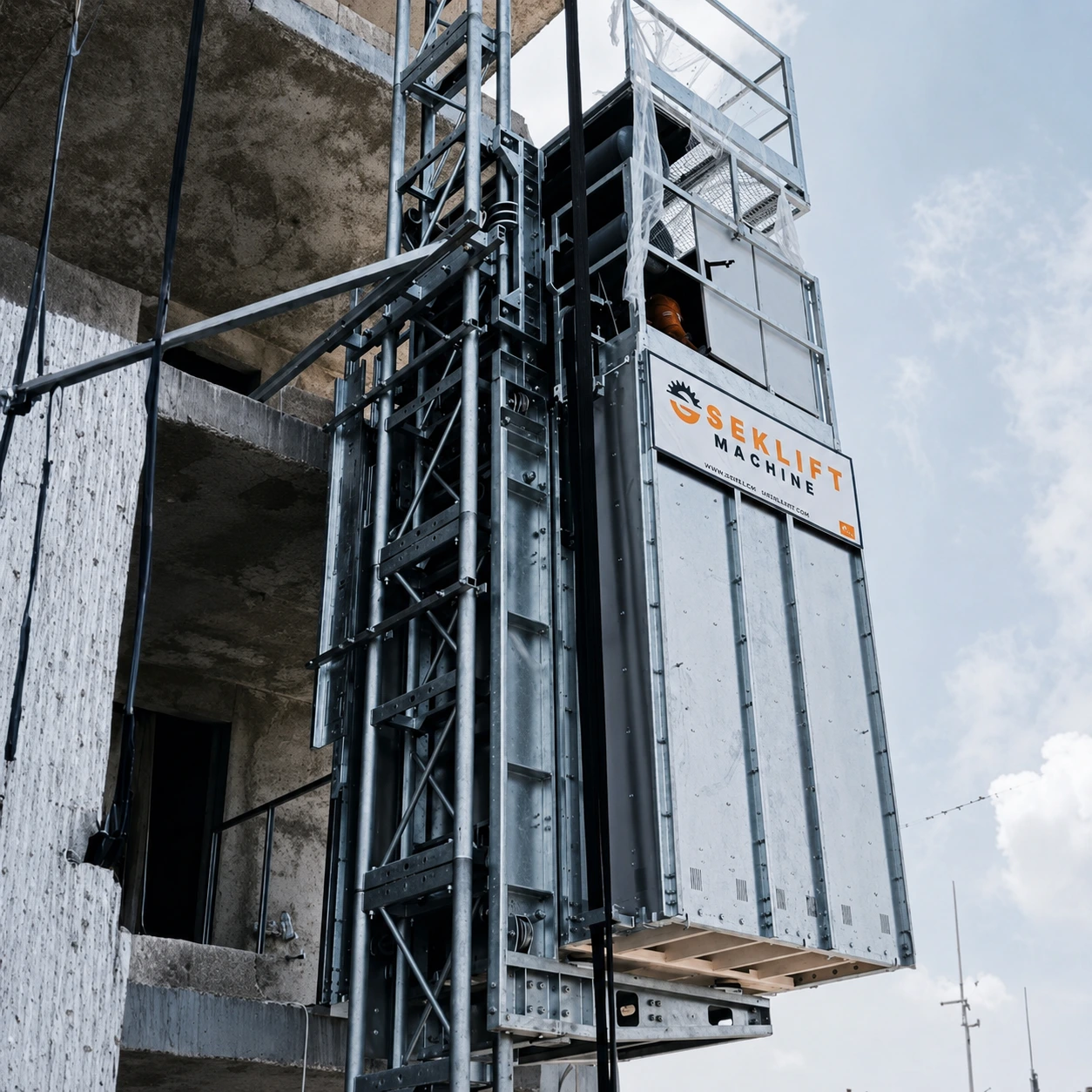 Mining Elevator Systems
Installation des SEKLIFT-Bergbauaufzugs für den vertikalen Zugang auf dem Minengelände.
Mine-hoist rope standards and regulations define different parts of the decision framework
Produktnormen, Prüfverfahren, behördliche Leitlinien und verbindliche Bergbauvorschriften erfüllen unterschiedliche Aufgaben. Produktnormen definieren die Lieferanforderungen für spezifizierte Seilkonstruktionen. Prüfnormen legen fest, wie eine Eigenschaft gemessen wird. Bergrecht, genehmigte Richtlinien und Betriebszulassungen regeln die Installation, Untersuchung, Prüfung und Demontage. Die Veröffentlichung einer Norm macht diese nicht in jedem Land rechtlich anwendbar, und ein Produktzertifikat weist nicht den aktuellen Seilzustand nach.
International and European standards
The ISO catalogue listed ISO 3154:1988, ISO 3155:1976, ISO 3156:1976 and ISO 5614:1988 as published/current documents when checked, while also showing review or revision activity for these older editions. ISO 3108:2017 remained the current test method for determining measured breaking force. ISO 4309:2017 remained published but was marked for revision, with successor work under development. Users should therefore verify the edition required by contract or law at the time of application. Standards status checked 3 September 2026.
- ISO 3154:1988 — technical delivery requirements for stranded mine-hoisting ropes within its stated scope.
- ISO 5614:1988 — technical delivery requirements for locked-coil mine-hoisting ropes.
- ISO 3155:1976 — characteristics and tests for fibre components used in stranded mine-hoisting ropes.
- ISO 3156:1976 — characteristics and tests for impregnating compounds, lubricants and service dressings.
- ISO 3108:2017 — tensile test method for determining measured breaking force.
- ISO 4309:2017 — care, maintenance, inspection and discard guidance for ropes on cranes, winches and hoists; supplementary for mine applications only when invoked by the applicable framework.
BSI listed BS EN 12385-1:2002+A1:2008, BS EN 12385-2:2002+A1:2008, BS EN 12385-6:2004 and BS EN 12385-7:2002 as current and under review when checked. Part 1 supplies general manufacturing and testing requirements; Part 2 defines terminology, designation and classification. Part 6 gives particular requirements for stranded and flat ropes for mine shafts and is used with Parts 1 and 2. Part 7 specifies additional materials, manufacturing and testing requirements for full-locked-coil hoist ropes and half- or full-locked-coil guide ropes for mine shafts to those given in Part 1, within the broader EN 12385 series framework. These are product standards, not universal in-service discard rules. (BSI: Part 1; Part 2; Part 6; Part 7)
United States: mine category and equipment scope matter
The earlier shorthand “U.S. metal/nonmetal provisions” is insufficient. Current federal rules use parallel but category-specific sections:
- 30 CFR Part 56 applies to surface metal and nonmetal mines.
- 30 CFR Part 57 applies to underground metal and nonmetal mines.
- 30 CFR Part 75 applies to underground coal mines.
- 30 CFR Part 77 applies to surface coal mines and surface work areas of underground coal mines.
Within the cited hoisting-rope provisions, §§56.19023, 57.19023, 75.1433 and 77.1433 require visual examination of the active rope length at least every 14 calendar days and, at least every six months, either nondestructive testing of the active length or prescribed diameter measurements at wear-prone locations. Daily examination applies to an affected portion when a visible condition may reduce strength. The corresponding removal sections—§§56.19024, 57.19024, 75.1434 and 77.1434—include diameter reduction due to wear exceeding 6% of the baseline diameter measurement and more than 10% rope-strength loss as determined by NDT, alongside broken-wire, corrosion, distortion and heat-damage criteria. The baseline is established after initial stretch but before visible wear under §§56.19022, 57.19022, 75.1432 and 77.1432. (30 CFR Parts 56 and 57; Parts 75 and 77)
Those percentages are U.S. regulatory removal criteria for ropes within the stated scope—not global material-failure thresholds. The Part 57 application provision and the cited Part 75 and Part 77 scope provisions expressly exclude wire ropes used for elevators; the detailed installation must therefore be classified correctly before any section is applied. They must not be transferred automatically to a mining elevator, a Turkish project or another jurisdiction.
United Kingdom, New South Wales and Türkiye
UK HSE's Steel wire ropes in vertical mine shafts is guidance for people who manufacture, select, install, inspect, examine or maintain winding, balance, guide and rubbing ropes. Its technical annexes address maintenance, deterioration and discard. It is authoritative guidance, not a universal statute or a substitute for current UK legal duties. (HSE)
The NSW Code of Practice: Mine shafts and winding systems, Version 2, April 2026, is an approved code of practice under section 274 of the NSW Work Health and Safety Act 2011. It guides principal-hazard management for underground mine shafts and winding systems, including lifecycle controls and ropes. It is admissible in proceedings and can evidence what is known about a hazard or control; it is not itself an exhaustive statement of the law, and equivalent or higher-standard methods may be used where the WHS framework permits. (NSW Resources Regulator, 2026)
This review did not establish, from an accessible authoritative source, a single Turkish mine-hoisting-rope regime that could be summarized safely across mine type and equipment category. The Turkish Koepe-rope field study cited above is research evidence, not legislation. Projects in Türkiye should verify current Turkish mining and occupational-safety legislation, applicable adopted TS EN standards, mine approvals and equipment classification with the competent authority and responsible engineer rather than importing U.S., UK or NSW thresholds.
For a real project, the controlling hierarchy normally begins with:
- Applicable mining and occupational-safety law and regulator requirements.
- Mine approvals, the winding-system safety case or principal-hazard plan, and applicable approved codes.
- Rope and winder manufacturers' instructions for the approved configuration.
- Applicable mine-rope product and test standards.
- General wire-rope guidance used only where the governing framework invokes or permits it.
Treat the rope as a monitored mechanical system
Mine-hoist wire-rope failure is best understood as a sequence, not a label. Dynamic loading, bending, torsion, contact geometry, lubrication and environment can initiate abrasive or adhesive wear, fretting, fatigue cracks, corrosion pits, internal breaks or localized metallic-area loss. As damage develops, load sharing changes. The remaining wires may ultimately fracture in ductile overload even when progressive deterioration began the loss of capacity.
That model does not make every failure progressive or identical. It explains why root cause cannot be read from one final fracture surface, one diameter value, one NDT trace, calendar age or nominal breaking force. Each indicator answers only part of the condition question.
For mine engineers and procurement teams, the practical implication is systems-based specification and evidence: match rope construction and grade to the winder and duty; verify product conformity; control installation twist and lubrication; preserve baseline measurements; trend location-specific visual and NDT findings; and apply the correct jurisdiction's examination and removal rules. Replacement decisions must remain project-specific and should be made by the competent mine or winding-system engineer under the applicable legal and approved technical framework.
Explore mine-site vertical access equipment for personnel, tools and material movement.
View mining elevators →Peer-reviewed literature
- Wang, D., Zhang, D. and Ge, S. 2013. “Determination of fretting parameters of hoisting rope in coalmine and fretting-fatigue behavior of steel wires.” Industrial Lubrication and Tribology, 65(6), 436–448. https://doi.org/10.1108/ILT-03-2011-0021
- Wang, D., Zhang, D., Zhang, Z. and Ge, S. 2012. “Effect of various kinematic parameters of mine hoist on fretting parameters of hoisting rope and a new fretting fatigue test apparatus of steel wires.” Engineering Failure Analysis, 22, 92–112. https://doi.org/10.1016/j.engfailanal.2012.01.008
- Peng, Y., Huang, K., Ma, C., Zhu, Z., Chang, X., Lu, H., Zhang, Q. and Xu, C. 2023. “Friction and wear of multiple steel wires in a wire rope.” Friction, 11(5), 763–784. https://doi.org/10.1007/s40544-022-0665-y
- Huang, K., Li, G., Chang, X., Zhou, Z., Peng, Y. and Deng, R. 2025. “Fretting friction and wear characteristics of the internal spiral contact steel wires in the hoisting wire rope under different service conditions.” Lubricants, 13(10), 453. https://doi.org/10.3390/lubricants13100453
- Wang, S., Zhang, D., Hu, N. and Zhang, J. 2016. “Effect of stress ratio and loading frequency on the corrosion fatigue behavior of smooth steel wire in different solutions.” Materials, 9(9), 750. https://doi.org/10.3390/ma9090750
- Wang, D., Zhu, Z. and Song, D. 2020. “Effects of tensile stress ratio and amplitude on tension-torsion fretting-corrosion-fatigue behaviors of non-perpendicularly crossed steel wires.” Engineering Failure Analysis, 117, 104839. https://doi.org/10.1016/j.engfailanal.2020.104839
- Singh, R. P., Mallick, M. and Verma, M. K. 2016. “Studies on failure behaviour of wire rope used in underground coal mines.” Engineering Failure Analysis, 70, 290–304. https://doi.org/10.1016/j.engfailanal.2016.09.002
- Schrems, K. K. 1994. “Wear-related fatigue in a wire rope failure.” Journal of Testing and Evaluation, 22(5), 490–499. https://doi.org/10.1520/JTE12670J
- Chang, X., Peng, Y., Zhu, Z., Gong, X., Yu, Z., Mi, Z. and Xu, C. 2019. “Breaking failure analysis and finite element simulation of wear-out winding hoist wire rope.” Engineering Failure Analysis, 95, 1–17. https://doi.org/10.1016/j.engfailanal.2018.08.027
- Chang, X., Shi, F., Chen, X., Peng, Y., Tang, Y., Xiao, W. and Hu, R. 2025. “Mechanical property degradation of transmission wire rope caused by different wear evolution.” Lubricants, 13(2), 59. https://doi.org/10.3390/lubricants13020059
- Zhang, D., Chen, K., Jia, X., Wang, D., Wang, S., Luo, Y. and Ge, S. 2013. “Bending fatigue behaviour of bearing ropes working around pulleys of different materials.” Engineering Failure Analysis, 33, 37–47. https://doi.org/10.1016/j.engfailanal.2013.04.018
- Zhang, D., Feng, C., Chen, K., Wang, D. and Ni, X. 2017. “Effect of broken wire on bending fatigue characteristics of wire ropes.” International Journal of Fatigue, 103, 456–465. https://doi.org/10.1016/j.ijfatigue.2017.06.024
- Onur, Y. A. 2012. “Condition monitoring of Koepe winder ropes by electromagnetic non-destructive inspection.” Insight—Non-Destructive Testing and Condition Monitoring, 54(3), 144–148. https://doi.org/10.1784/insi.2012.54.3.144
- Tytko, A., Olszyna, G., Rokita, T. and Skrzypkowski, K. 2025. “Strength tests of selected ropes used in mining shaft hoists after their replacement in stochastic interpretation.” Materials, 18(17), 4217. https://doi.org/10.3390/ma18174217
- Peterka, P., Krešák, J., Kropuch, S., Fedorko, G., Molnar, V. and Vojtko, M. 2014. “Failure analysis of hoisting steel wire rope.” Engineering Failure Analysis, 45, 96–105. https://doi.org/10.1016/j.engfailanal.2014.06.005
- Hu, Z., Wang, E., Jia, F. and Dong, M. 2023. “Experimental study on effect of additional torsional load on bending fatigue behavior and failure mechanism of steel wire rope.” International Journal of Fatigue, 167, 107399. https://doi.org/10.1016/j.ijfatigue.2022.107399
Standards and regulatory sources
- International Organization for Standardization (ISO). ISO 3154:1988, Stranded wire ropes for mine hoisting—Technical delivery requirements. Status checked 3 September 2026: Published; current edition; review stage 90.60. ISO
- International Organization for Standardization (ISO). ISO 3155:1976, Stranded wire ropes for mine hoisting—Fibre components—Characteristics and tests. Status checked 3 September 2026: Published; current edition; review stage 90.60. ISO
- International Organization for Standardization (ISO). ISO 3156:1976, Stranded wire ropes for mine hoisting—Impregnating compounds, lubricants and service dressings—Characteristics and tests. Status checked 3 September 2026: Published; review stage 90.60. ISO
- International Organization for Standardization (ISO). ISO 3108:2017, Steel wire ropes—Test method—Determination of measured breaking force. Status checked 3 September 2026: Published; confirmed in 2023 and current. ISO
- International Organization for Standardization (ISO). ISO 4309:2017, Cranes—Wire ropes—Care and maintenance, inspection and discard. Status checked 3 September 2026: Published/current; marked “to be revised” at stage 90.92, with ISO/CD 4309 under development. ISO
- International Organization for Standardization (ISO). ISO 5614:1988, Locked coil wire ropes for mine hoisting—Technical delivery requirements. Status checked 3 September 2026: Published; review stage 90.60. ISO
- British Standards Institution (BSI) / European Committee for Standardization (CEN). BS EN 12385-1:2002+A1:2008, Steel wire ropes—Safety—Part 1: General requirements. Status checked 3 September 2026: Current, under review. BSI
- British Standards Institution (BSI) / European Committee for Standardization (CEN). BS EN 12385-2:2002+A1:2008, Steel wire ropes—Safety—Part 2: Definitions, designation and classification. Status checked 3 September 2026: Current, under review. BSI
- British Standards Institution (BSI) / European Committee for Standardization (CEN). BS EN 12385-6:2004, Steel wire ropes—Safety—Part 6: Stranded ropes for mine shafts. Status checked 3 September 2026: Current, under review; used in conjunction with Parts 1 and 2. BSI
- British Standards Institution (BSI) / European Committee for Standardization (CEN). BS EN 12385-7:2002, Steel wire ropes—Safety—Part 7: Locked coil ropes for mine shafts. Status checked 3 September 2026: Current, under review; specifies additional mine-shaft locked-coil requirements to those given in Part 1, within the broader EN 12385 series framework. BSI
- Mine Safety and Health Administration (MSHA). 30 CFR Part 56, surface metal/nonmetal mines, Subpart R—Personnel Hoisting. Current eCFR text checked 3 September 2026. eCFR
- Mine Safety and Health Administration (MSHA). 30 CFR Part 57, underground metal/nonmetal mines, Subpart R—Personnel Hoisting. Current eCFR text checked 3 September 2026. eCFR
- Mine Safety and Health Administration (MSHA). 30 CFR Part 75, underground coal mines, §§75.1430–75.1434. Current eCFR text checked 3 September 2026. eCFR
- Mine Safety and Health Administration (MSHA). 30 CFR Part 77, surface coal mines and surface work areas of underground coal mines, §§77.1430–77.1434. Current eCFR text checked 3 September 2026. eCFR
- Mine Safety and Health Administration (MSHA). Program Information Bulletin P09-10, Non-Destructive Testing of Mine Hoist Ropes. Official MSHA source. MSHA
- UK Health and Safety Executive (HSE). Guidance on the selection, installation, maintenance and use of steel wire ropes in vertical mine shafts. Guidance; current HSE guidance page checked 3 September 2026. HSE
- NSW Resources Regulator. 2026. NSW Code of Practice: Mine shafts and winding systems, Version 2, April 2026. Approved code of practice under section 274 of the Work Health and Safety Act 2011. Official PDF
Standards and regulatory status checked 3 September 2026. Applicable editions, national adoptions and legal requirements must be verified for each project.