
Sistem de acces pentru fațade BMU și întreținerea clădirilor
SEKLIFT proiectează sisteme BMU pentru acces permanent la fațadele clădirilor. Aceste soluții sunt utilizate pentru curățare, inspecție și întreținere periodică și sunt configurate în funcție de geometria acoperișului, parapete, forma fațadei și zonele de lucru necesare.
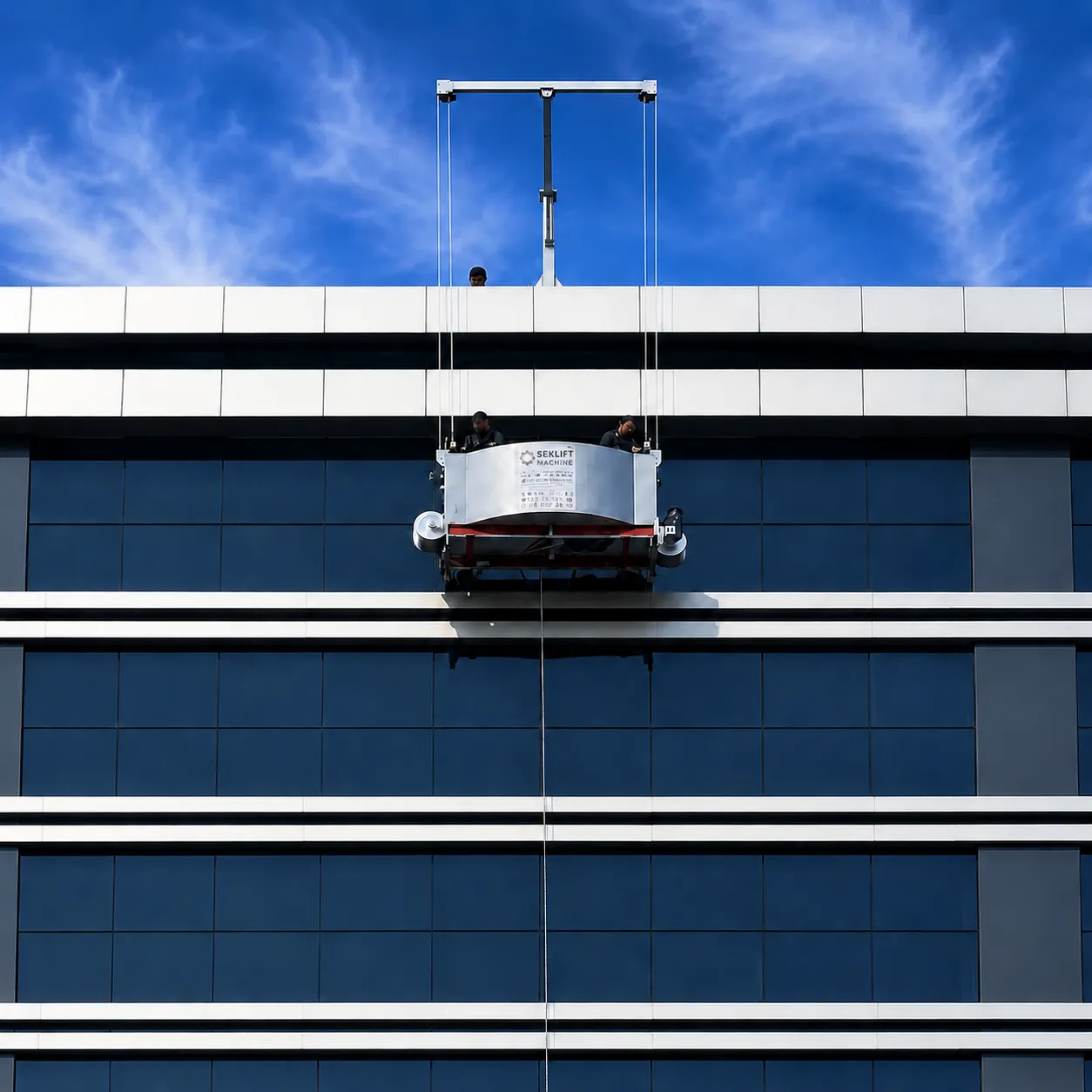
- 01Window Cleaning
- 02Façade Inspection
- 03Joint & Sealant Work
- 04Cladding Maintenance
- 05High-Rise Building Care
SK-TAP-101 — sistem permanent de acces și întreținere a fațadelor
BMU Systems & Building Maintenance Unit Planning
SK-TAP-101 combines a 2 m suspended façade-cleaning platform, twin electric drives, galvanized wire ropes, dual rope winding and independent operating safeguards in one coordinated maintenance-access system.
Roof interface, suspension arrangement, anchorage, outreach, parking and rescue planning must be engineered for the actual building.SUSPENDED FAÇADE CLEANING & MAINTENANCE PLATFORM
SEKLIFT SK-TAP-101 Facade Cleaning System
A 500 kg façade-cleaning platform with a 2 m working deck, twin 1.1 kW motors and two rope-winding mechanisms. Its 0.15 m/s climbing speed, 8 mm galvanized wire ropes and coordinated emergency systems support controlled access for high-rise building maintenance.
Verified for this model: 500 kg rated capacity, 2 × 1.1 kW motors, 0.15 m/s vertical speed and a 2 m platform. Confirm roof interface, suspension geometry, support loads, parking, rescue access and the complete selected configuration through project-specific review.
- Capacitate nominală
- 500 kg
- Puterea motorului
- 2 × 1.1 kW
- Viteză verticală
- 0.15 m/s
- Lungimea peronului
- 2 m
Safety Architecture. Protected Throughout Travel.
SK-TAP-101 coordinates its powered 2 m platform with electromagnetic braking, secondary rope protection, inclination monitoring, travel limits, overload detection and a manual power-loss lowering procedure.
An electromagnetic brake and two block-stop brakes provide the stated stopping and secondary rope-protection layer.
The red emergency control stops operation, while the manual system allows controlled lowering after a power failure.
A 14° tilt limit, upper and lower limit switches, and overload detection monitor the operating envelope.
The dedicated platform dimension provides a compact working zone for façade cleaning and maintenance personnel.
The stated suspension specification uses 8 mm, 6×19 galvanized wire ropes.
Two rope-winding units coordinate with the twin-drive platform configuration.
The supplied electrical specification states a 380 V operating voltage.
Roof layout, suspension position, façade recesses, working zones, parking and rescue access must be coordinated for the individual structure.
Define the Maintenance Envelope Before Final Configuration.
The suspended platform is only one part of the final arrangement. A useful engineering review begins with the actual structure: roof plan, elevations, sections, parapet geometry, working height, façade recesses, obstacles, intended duties and the position where the equipment will be parked. These inputs establish the physical envelope that the suspension layout, support points and operating route must work within.
Coordinate Suspension Geometry with the Structure
Roof conditions determine where supporting equipment can be positioned and how the suspended platform reaches the required working zones. Parapets, setbacks, available structural space, anchorage conditions and support loads should therefore be reviewed together rather than treated as separate details. Parking position and the route used to prepare the equipment for operation also need to be considered during this stage.
Map Working Zones, Obstacles and Travel Requirements
Building elevations and section drawings help identify recesses, projections, changes in geometry and areas that require regular cleaning or inspection. The proposed arrangement should account for these conditions before the operating concept is finalized. This review also gives the project team a clearer basis for discussing working height, maintenance duties and how the platform is expected to approach each required zone.
Plan Power, Parking and Emergency Procedures Together
The supplied equipment specification states 380 V operation together with braking, travel-limit, tilt, overload and manual-lowering provisions. Their project use still has to be coordinated with the building arrangement, normal operating procedure, parking location and rescue planning. Bringing these requirements into the same review helps avoid treating mechanical, electrical and operational interfaces as unrelated decisions.
Identify roof constraints, façade zones, recesses, obstacles, parking position and rescue requirements.
Review support loads, suspension geometry, 380 V supply and the interface between the building and access equipment.
Braking, rope protection, tilt, limit and overload systems form the supplied safety architecture.
Choose by Use, Building Interface and Project Duty.
These systems solve different access problems. Selection should follow the work period, façade geometry, loads, building interface and operating plan—not a single maximum specification.
| Decision factor | Platforme de lucru autoridicătoare pe catarg | Platforme suspendate electrice | Permanent BMU / Façade Access |
|---|---|---|---|
| Use period | Temporary, project-period access. | Temporary and redeployable access. | Permanent, building-specific access. |
| Primary duty | Construction, renovation and defined elevated façade work. | Construction, cladding, glazing, finishing, inspection and maintenance. | Routine façade cleaning, inspection and building maintenance. |
| Load / platform | Single- or twin-mast platforms configured by SM-SK model, span and load distribution. | SM-GAP-101: 500 kg; 1.5, 3, 4.5 or 6 m modular platform options. | SK-TAP-101: 500 kg; 2 m working platform. |
| Building interface | Mast, chassis, anchoring and landing or working-zone coordination. | Roof or suspension rig, anchorage and counterweight arrangement. | Permanent roof/building interface, suspension geometry, support and parking. |
| Installation complexity | Medium to high; mast, base and anchors require project coordination. | Moderate; demountable, but suspension and roof conditions require review. | Highest; integrated with the building and maintenance strategy. |
| Mobility / repositioning | Repositioned by dismantling or reconfiguration. | Transportable and redeployable; lateral repositioning is manual. | Movement is limited to the engineered building-access envelope. |
| Engineering inputs | Façade length, height, payload, load distribution, base, anchors and power. | Platform length, working height, roof geometry, suspension, power and duty. | Roof plan, elevations, support loads, outreach, parking, power and rescue access. |
| Typical buyer / user | Contractor or specialist access company. | Contractor, façade installer or maintenance provider. | Building owner, consultant or facilities-management team. |
| When not to choose | Not for permanent building-integrated maintenance or where mast/anchor interfaces are unsuitable. | Not where a permanent system is required or roof/suspension conditions are unsuitable. | Not as short-term construction access or before the building interface is defined. |
Project-specific review required. Final suitability, interfaces and documentation must be confirmed for the selected configuration and actual building.
Engineer SK-TAP-101 around the actual building.
Share the building elevations, roof plan, section drawings, parapet geometry, working height, maintenance zones, parking position and intended duties so SEKLIFT can review the façade-access concept.
