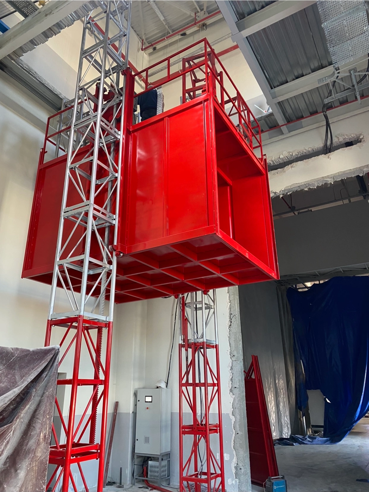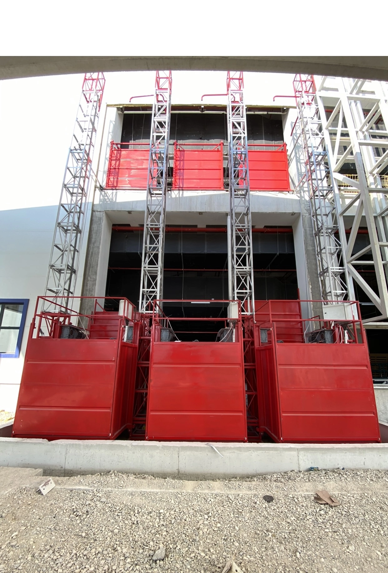
Причины выхода из строя подъемных канатов шахтных подъемных установок: усталость, износ, коррозия и перераспределение нагрузки
Why mine-hoist wire ropes fail: fatigue, wear, corrosion, load redistribution, inspection limits, and the standards that guide safe decisions.
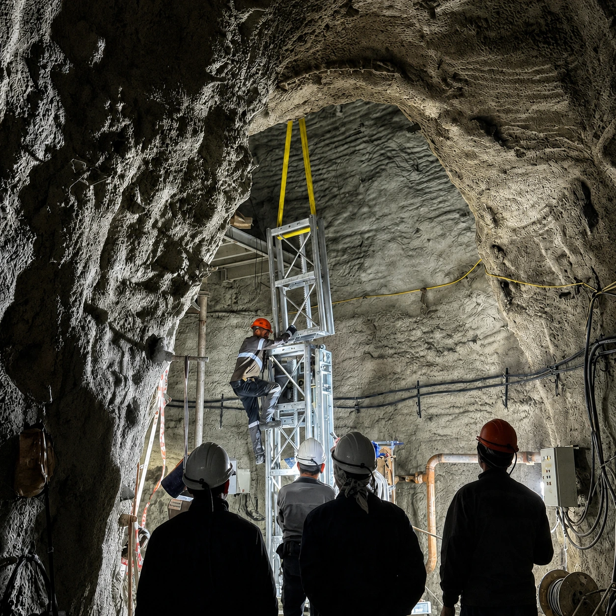
A mine-hoist wire rope is not a solid steel bar. It is a moving assembly of helically laid wires and strands. During each winding cycle, those elements carry changing tension, bend over sheaves or onto drums, twist, press against adjacent wires and undergo small relative movements. The result is a distributed mechanical system in which damage may begin at a surface, an internal contact, a corrosion pit or a local defect before it becomes visible at rope scale.
The final fracture therefore does not necessarily identify the initiating cause. Progressive wear, fatigue, corrosion or earlier wire breaks can reduce effective load-bearing capacity. Full-rope experiments further show that wear and broken wires can redistribute load so that surviving wires may ultimately fail by ductile overload. Conversely, a severe one-time overload, attachment failure or material nonconformity can produce a different history. Understanding mine hoist wire rope failure therefore requires distinguishing the initiating degradation mechanism from damage propagation, loss of effective section and the final fracture mode. (Schrems, 1994; Chang et al., 2019; Zhang et al., 2017; Singh, Mallick and Verma, 2016)
How the evidence was reviewed
Настоящая статья представляет собой научно обоснованный инженерный обзор, а не систематический обзор, метаанализ или исчерпывающий литературный обзор. Целевые поисковые запросы выполнялись по базам данных издательств журналов и записям DOI по темам динамики шахтных подъёмников, фреттинг-коррозии канатных проволок, усталости при изгибе, износа, коррозионной усталости, кручения, перераспределения нагрузки при обрыве проволок, экспертных исследований отказов, электромагнитного контроля и испытаний на остаточную прочность. Поиск и проверка стандартов были завершены 3 сентября 2026 года. Приоритет отдавался оригинальным рецензируемым исследованиям, данным по конкретным шахтным установкам, натурным испытаниям канатов и авариям в процессе эксплуатации; испытания отдельных проволок и многопроволочных образцов учитывались только для выводов на уровне механизмов. Официальные каталожные записи ISO и BSI, актуальный текст регламента eCFR, материалы MSHA, руководства Управления по охране труда и промышленной безопасности Великобритании (HSE) и утвержденный в апреле 2026 года свод правил Нового Южного Уэльса (NSW) проверялись отдельно.
В число репрезентативных поисковых комбинаций входили следующие: “рудничный подъемный канат”, “усталость рудничного подъемного каната”, “фреттинг стального каната”, “коррозионная усталость рудничного каната”, “усталость при изгибе стального каната”, “неразрушающий контроль канатности подъемных машин системы Кепе”, “перераспределение нагрузки при обрыве проволок”, “осмотр канатов шахтных стволов” и “анализ отказов рудничных подъемных канатов”. Исследования отбирались в тех случаях, когда они непосредственно касались динамики рудничных подъемов, механизмов повреждения канатов или проволок, расследования отказов, контроля состояния или интерпретации остаточной прочности. Общие исследования стальных канатов отходили на второй план, за исключением случаев отсутствия данных, специфичных для шахтных условий, или необходимости уточнения механизмов. Списки литературы и цепочки цитирования из соответствующих первичных работ выборочно проверялись с целью поиска дополнительных первоисточников.
Типы доказательств выявляются в тексте, поскольку математическая модель, испытание на сетевом уровне, ускоренный эксперимент с канатом полной длины, криминалистический случай и правовой порог отвечают на разные вопросы. Противоречивые результаты интерпретировались с учетом масштаба испытаний, нагрузки, условий среды, а также того, измерялось ли в исследовании зарождение или распространение трещины. Несколько цитируемых экспериментальных работ подготовлены аффилированными друг с другом исследовательскими группами Китайского горно-технологического университета; они представляют собой единую согласованную научно-исследовательскую программу, а не множество независимых репликаций. Независимые данные криминалистической экспертизы, полевого мониторинга и испытаний вышедших из эксплуатации канатов из США, Индии, Турции, Польши и Словакии расширяют данное ограничение, но не устраняют его полностью.
A mine winding rope experiences a load history, not one static load
Номинальная подвесная нагрузка не отражает полную эксплуатационную нагрузку, приходящуюся на шахтный подъемный канат. Ускорение, замедление, вибрация, изменение длины подвеса, изгиб, кручение и эксплуатационные переходные процессы изменяют как натяжение в системе, так и местные условия в точках контакта проволок.
Моделирование системы, выполненное Ван, Чжаном и Гэ, наглядно демонстрирует различие между глобальным и локальным масштабами. Для одной конкретной модели подъемника угольной шахты авторы рассчитали динамическое натяжение каната в диапазоне от 0 до 30,9 кН. Затем они определили отдельные значения нагрузок на местах соприкосновения проволок: 38,3; 60,5; 102,7 и 378 Н, а также относительные смещения в 62,5 и 113,2 мкм в определённых точках соприкосновения. Эти данные были получены в результате моделирования для последующих испытаний тросов — это не полевые измерения, не расчётные нагрузки и не предельные значения, применимые к другому шахтному стволу. Их значение носит концептуальный характер: крупномасштабные движения подъёмной системы могут генерировать внутренние перемещения малой амплитуды, способные привести к износу от трения. (Ван, Чжан и Гэ, 2013; Ван и др., 2012)
Глубина ствола имеет значение, поскольку более длинный подвешенный канат увеличивает собственный вес и изменяет динамическую характеристику системы. Сама по себе глубина не является причиной выхода из строя; она действует в совокупности с массой каната, полезной нагрузкой, профилем скорости, типом подъемной машины, геометрией и режимом работы. Использование в правилах безопасности для горнодобывающей промышленности формул минимальной прочности, зависящих от длины, отражает эту изменяющуюся проектную задачу, однако законодательно установленная формула запаса прочности не является прогнозом вероятности выхода из строя конкретного каната.
Пребывание ниже номинального предела полезной нагрузки, следовательно, не исключает циклическое повреждение. Состояние зависит от спектра нагрузок и системы канат-подъемная машина, а не только от наибольшей статической нагрузки.
Bending and internal contact create repeated local damage
Канат должен изгибаться при огибании шкива или при наматывании на барабан. Такая повторяющаяся кривизна приводит к первичному изгибу каната, а также к вторичному изгибу и контактным напряжениям на уровне проволок. Соседние проволоки и пряди также прижимаются друг к другу и смещаются относительно друг друга. Эти механизмы могут действовать одновременно, поэтому “усталость” не следует рассматривать как единый однородный процесс.
В ходе ускоренного эксперимента с использованием полной длины каната, проведённого Чжаном и его коллегами, канат с волокнистым сердечником 6×19 неоднократно подвергался изгибу на стальных и модифицированных нейлоновых шкивах. В данной экспериментальной установке канат, использованный с модифицированным нейлоновым шкивом, продемонстрировал срок службы при изгибной усталости, превышающий более чем в два раза заявленный показатель для каната, использованного со стальным шкивом. Исследование демонстрирует, что материал шкива и характер контакта могут влиять на развитие повреждений. Оно не устанавливает универсального коэффициента увеличения срока службы: конструкция каната, диаметр и канавка шкива, нагрузка, скорость, условия эксплуатации, а также ограниченный объём выборки в эксперименте ограничивают возможность обобщения полученных результатов. (Чжан и др., 2013)
Nor does the result prove that synthetic sheaves are inherently safer. ISO 4309:2017, which covers crane, winch and hoist ropes rather than serving as the default mine-shaft rope standard, warns that systems using exclusively synthetic sheaves or synthetic linings with single-layer drum spooling can accumulate internal wire breaks before adequate external evidence appears. The defensible lesson is that the rope and sheave form an interacting contact system: changing material or geometry can change both the damage rate and where damage becomes detectable. (ISO 4309:2017)
Fretting: lower friction or slip does not necessarily mean less damage
Fretting is surface damage caused by small, repeated relative motion under contact load. In a rope it can occur between individual wires or between strands. Fretting wear removes material; fretting fatigue describes crack initiation and growth promoted by that cyclic contact. Fretting corrosion additionally involves chemical or electrochemical surface reactions. These terms are related but not interchangeable.
In a forensic examination of a non-rotating skip-hoist rope from an underground mine, Schrems found failures associated with interstrand wear and fatigue. Fractography also showed why the most obvious wear scar need not coincide with the exact crack origin: cracks may begin where the local multiaxial stress state is most damaging, including a less visually dramatic location. This is one service failure, not evidence of population-wide frequency, but it is direct mine-rope evidence that visible metal loss alone can be an incomplete root-cause indicator. (Schrems, 1994)
Controlled multi-wire experiments by Peng and colleagues used a seven-wire helical assembly—six 1 mm outer wires around a 1.1 mm core—under dry laboratory conditions. As lateral load increased from 80 to 320 N, the reported steady coefficient of friction fell from about 0.73 to 0.66, while maximum wear depth increased from 10.9 to 23.1 μm and average wear width from 111.5 to 135.8 μm. These are reported results for the study's wire geometry, tension, fretting amplitude and environment; they are not mine-rope service limits. The experiment supports a narrower conclusion: lower measured friction can coexist with greater wear because normal load, contact stress and dissipated energy also change. (Peng et al., 2023)
Other multi-wire tests from the same wider research lineage show that frequency, wire tension and helical-contact geometry can change friction and wear. These studies improve mechanism understanding but should not be counted as independent field replication, and their test rigs do not reproduce every contact in a full rope. (Huang et al., 2025)
The correct conclusion is not that lower friction causes more damage. It is that friction coefficient or relative slip alone cannot represent rope health. Contact pressure, stress distribution, debris, lubrication, evolving scar geometry and the transition among adhesion, partial-slip and gross-slip regimes also matter.
External wear removes metal and can shorten later fatigue life
External wear at a sheave, groove or multilayer-drum crossover is not merely cosmetic. It reduces metallic area, changes local geometry, concentrates stress and disturbs load sharing. Diameter reduction, loss of metallic area and residual breaking force are related condition indicators, but they are not equivalent measurements.
Chang and colleagues conducted an accelerated full-rope study on a 9.3 mm 6×19 fibre-core transmission rope whose initial measured breaking force was 52.5 kN. Under the most severe rope–sheave wear sequence reported, breaking force declined from approximately 48 to 23 kN and subsequent bending-fatigue endurance from about 6,200 to 200 cycles. These values describe test endpoints in one small-rope rig using a Q235 sheave. They are not expected mine-shaft service lives, uncertainty bounds or discard criteria; the paper does not establish that the same percentage loss occurs in a full-size mine winding rope. (Chang et al., 2025)
In the same research programme, a rope–rope wear sequence reduced breaking force from about 50 to 46 kN, a smaller change than in that study's rope–sheave sequence. It would be unsound to generalize that rope–sheave wear is always more severe: the rigs represented different contacts and used different loads, speeds and contact lengths. The comparison is conditional on the experimental arrangements.
Controlled-wear and finite-element work has further shown that groove-shaped or irregular scars can produce non-uniform stress and load sharing. Yet the Schrems service failure showed that the deepest visible loss does not invariably locate the fatigue origin. Average diameter can therefore miss a deep local scar, an unfavourable scar orientation, clustered breaks or internal damage. (Chang et al., 2019; Schrems, 1994)
Lubrication changes the contact regime; it does not eliminate fatigue
Suitable lubrication can reduce friction and wear and can contribute to corrosion protection under appropriate conditions. In Peng and colleagues' seven-wire test system, the steady coefficient of friction was about 0.16–0.22 with the tested oil versus roughly 0.58–0.75 under dry conditions. Reported dry wear widths were approximately 160–240 μm, compared with about 40–120 μm in lubricated tests. The observed mechanisms also changed: dry contacts showed abrasive, adhesive and fatigue wear, while lubricated contacts were dominated more by abrasive and fatigue processes. (Peng et al., 2023)
That result demonstrates a protective effect under the tested conditions, not a universal lubricant specification or relubrication interval. It used one laboratory lubricant and a small multi-wire assembly, not an operating mine rope. Lubricant chemistry, viscosity, application method, contamination and compatibility with the rope core and surface finish all affect performance.
Friction-winding or Koepe systems introduce an additional constraint: traction between rope and the drive sheave or drum is part of the system design. UK HSE guidance states that externally applied lubricants or dressings on friction-winder ropes must not significantly reduce the coefficient of friction between the rope and driving drum and warns against over-lubrication because it can cause rope slip or uneven travel. More lubricant is therefore not automatically safer, and an unsuitable dressing may conflict with traction requirements. (HSE) UK HSE shaft-rope guidance also notes that external lubricant can restrict the penetration of dirt and grit that would otherwise increase abrasion, while excessive use of a sticky lubricant can attract grit and reduce rope life. This is general shaft-rope guidance, not a finding of the Peng experiment. Rope and winder manufacturers' instructions, the approved winding-system design and the governing mine rules should control the specification and application practice. (HSE)
Forensic analysis of two ropes used in underground coal mines reported poor lubrication together with wear and corrosion. This supports inadequate lubrication as a contributing condition in those cases, not as a sole cause or the dominant cause across mines. (Singh, Mallick and Verma, 2016)
ISO 3156:1976 addresses characteristics and tests for impregnating compounds, lubricants and service dressings used with stranded mine-hoisting ropes. It is a materials-and-test standard; it does not provide one field relubrication interval for every shaft.
Corrosion and fatigue interact; pH alone does not predict rope life
Corrosion may remove metal, create pits and disrupt protective surface conditions. Under cyclic loading, pits and other surface defects can concentrate stress and become crack-initiation sites. Corrosion fatigue is therefore a coupled process: the environment changes the surface from which mechanical cracking may begin, while cyclic deformation and contact repeatedly disturb that surface.
Wang and colleagues tested smooth 1 mm wires taken from a 6×19 mine rope. The wire had a reported ultimate tensile strength of 1,750 MPa and was tested in laboratory solutions with pH values of 2.97, 6.97 and 9.97. The acidic solution produced the shortest fatigue lives among the conditions examined. This wire-level result supports the effect of that solution chemistry on crack initiation; it does not show that acid mine water alone causes full-rope failure or that pH is a sufficient environmental descriptor. (Wang et al., 2016)
The same study shows why fatigue-cycle figures require restraint. At a maximum stress of 800 MPa in the neutral solution, the study reported approximately 72,000 cycles at 2 Hz and stress ratio R = 0.5, versus about 5,700 cycles at 5 Hz and R = 0.05. These were test results for smooth 1 mm wires in specified solutions—not a service-life range for mine ropes. Fatigue endurance also commonly exhibits scatter, and the article did not report these two values as universal population means.
Results from other corrosion-fatigue studies may appear to conflict when they measure different stages. Smooth-wire tests include crack initiation; pre-cracked specimens emphasize propagation. Frequency changes exposure time per cycle, stress ratio changes mean stress and crack closure, and solution chemistry involves more than pH. A trend observed for initiation cannot automatically be applied to crack growth in a full rope.
Crossed-wire tension–torsion fretting-corrosion experiments add another complication. In one study, mechanical indicators such as dissipated energy, wear depth and crack-propagation measures increased under certain loading changes while the electrochemical-corrosion response moved in the opposite direction. Mechanical wear and electrochemical reaction are distinct damage channels; intensifying one need not increase the other. This was a crossed-wire laboratory study, not a field rope. (Wang, Zhu and Song, 2020)
The defensible engineering conclusion is conditional: corrosion-fatigue response depends on solution chemistry, exposure time, stress amplitude and ratio, frequency, rope construction, lubrication and pre-existing damage.
Torsion, installation and material conformity add different risks
Residual or imposed torsion
Torsion changes how helically arranged wires and strands press, slide and bend against one another. In accelerated full-rope bending tests, Hu and colleagues imposed twisting and untwisting and reported an approximately linear reduction in bending-fatigue endurance across their tested angular range. Both directions increased elongation, while twisting was more damaging than untwisting in that configuration. (Hu et al., 2023)
That ordering is not universal. Laboratory-imposed torsion is not identical to every installation error or source of service rotation, and the response depends on rope construction, lay direction, load and rig geometry. The supported conclusion is that residual or imposed torsion can alter internal contact, wear-scar development and bending-fatigue endurance. Installation and rope replacement should therefore control twist in accordance with the rope and winder documentation.
Material and manufacturing conformity
Premature damage can also result when the supplied rope does not match its declared material or construction. Peterka and colleagues examined a prematurely damaged drilling-hoist rope and an unused reserve sample. Their forensic and metallurgical analysis found that the rope was manufactured in a grade different from the declared 1,770 MPa class. Mixed-strength wires in the outer strand layer deformed differently; lower-strength wires released, rolled and fractured after short service. (Peterka et al., 2014)
This is a single drilling-hoist case, not evidence that manufacturing nonconformity is a common mine-shaft failure cause. It does show why procurement needs more than a nominal breaking-force entry: rope construction, grade, lay, coating, core, lubrication, test certificates and acceptance evidence must match the approved duty.
ISO 3154:1988 specifies technical delivery requirements for stranded mine-hoisting ropes within its scope; ISO 5614:1988 performs a comparable role for locked-coil mine-hoisting ropes. EN 12385-6 provides particular requirements for stranded mine-shaft ropes within the EN 12385 framework, while EN 12385-7 specifies additional requirements for full-locked-coil hoist ropes and half- or full-locked-coil guide ropes for mine shafts. Conformity at delivery is necessary, but it does not establish in-service condition after installation.
Broken wires change the load path before final rupture
A broken wire is not only a count. Once it stops carrying its intended share, forces and stresses redistribute through the remaining structure. Damage location and clustering can therefore matter as much as the total number of breaks.
Zhang and colleagues introduced controlled surface-wire break patterns into full ropes and subjected them to repeated bending. The tests and associated analysis showed increased inner-strand stresses and contact forces after surface breaks. Among the configurations tested, a concentrated 1×4 pattern produced the most severe response. This does not make four adjacent breaks a universal discard threshold: the defects were manufactured in one rope construction, and legal criteria depend on rope type, reference length and jurisdiction. The study supports the mechanism-level conclusion that concentrated damage can be more consequential than the same number of separated breaks. (Zhang et al., 2017)
В том же исследовании были выделены разломы, вызванные износом или усталостью, в отличие от пластической перегрузки в проволоках, сохранившихся до момента окончательного разрушения. Испытания с контролируемым износом продемонстрировали аналогичную последовательность: сначала разрушались сильно изношенные наружные проволоки, а затем внутренние проволоки принимали на себя измененные нагрузки. Именно поэтому пластическая перегрузка на последних сохранившихся проволоках не является автоматическим доказательством того, что причиной события послужила чрезмерная полезная нагрузка. Это может быть конечным типом разрушения после того, как прогрессирующее повреждение привело к уменьшению эффективного сечения. (Chang et al., 2019)
Эта последовательность не является неизбежной. Разовые перегрузки, отказ крепления, ударное воздействие или дефект материала могут породить иную цепь событий. Имеющиеся данные убедительно свидетельствуют в пользу разграничения инициирующего механизма деградации и конечного характера разрушения при проведении расследования причин отказов.
Mine-hoist rope inspection: appearance, age and nominal capacity cannot establish complete condition
Визуальный осмотр незаменим, однако поверхность не может выявить каждый внутренний дефект. Измерение диаметра позволяет определить определенные виды износа или деформации, в то время как методы электромагнитного контроля или контроля рассеяния магнитного потока могут указывать на локальные дефекты и уменьшение площади поперечного сечения металла. Ни уменьшение диаметра, ни результат неразрушающего контроля сами по себе не являются прямым измерением остаточной разрывной прочности.
Испытания на разрушение списанных тросов, проведенные Тытко и его коллегами, наглядно демонстрируют, почему календарный возраст также является неполноценным показателем. Один трос диаметром 60 мм с пластиковой пропиткой, снятый через 50 месяцев, продемонстрировал, согласно отчету, снижение суммарной разрывной силы его проволок на 7,91 TP3T. Другой канат диаметром 61 мм, демонтированный через 48 месяцев, продемонстрировал снижение суммарной прочности проволок примерно на 20% и снижение разрывной силы всего каната на 23,25%. Речь идет о результатах наблюдений за двумя разными канатами, а не о статистически репрезентативном сравнении или о правиле замены через четыре года. Стохастический анализ, проведенный в рамках данного исследования, также подтверждает, что результаты по прочности проволок представляют собой распределения, а не единичное детерминированное значение. (Tytko et al., 2025)
Онур представил отчет о трёх сериях электромагнитных обследований на месте четырёх головных тросов Копе с треугольной скруткой 6×37 и диаметром 38 мм на шахте "Козлу № 1" в Турции. В ходе работ отслеживались признаки потери металлической площади и локализованных дефектов, а также рассчитывалось их влияние на коэффициент безопасности. При этом не проводилась разрушающая проверка каждого признака и не устанавливалась универсальная зависимость между амплитудой сигнала и остаточной прочностью. На интерпретацию результатов влияют такие факторы, как оборудование, намагничивание, калибровка, конструкция троса, скорость и геометрия дефекта. (Онур, 2012)
В бюллетене MSHA P09-10 описывается трос служебного ствола, в котором значительные внутренние точечные коррозионные повреждения и коррозия не были должным образом выявлены при измерении диаметра в точке и испытаниях на разрыв. В бюллетене рекомендуется в соответствующих случаях проводить электромагнитное исследование, поскольку в противном случае внутреннее изношение может остаться незамеченным. В нем не указывается, что электромагнитное исследование заменяет визуальный осмотр. Визуальный осмотр по-прежнему необходим для выявления видимых обрывов проволок, коррозии, деформаций, повреждений от перегрева, локального износа и состояния креплений. (MSHA PIB P09-10)
Оценка состояния должна, следовательно, сочетать взаимодополняющие показатели и тенденции, как это требуется для конкретной установки. В зависимости от действующего режима это может включать результаты визуального контроля с привязкой к местоположению, исходные и последующие измерения диаметра, распределение обломанных проволок, признаки потери площади металла и локальных дефектов, разрушающие испытания или испытания на образцах, историю эксплуатации и изменения с течением времени. Возраст, номинальное усилие разрыва, средний диаметр или один результат неразрушающего контроля не должны рассматриваться как исчерпывающая оценка.
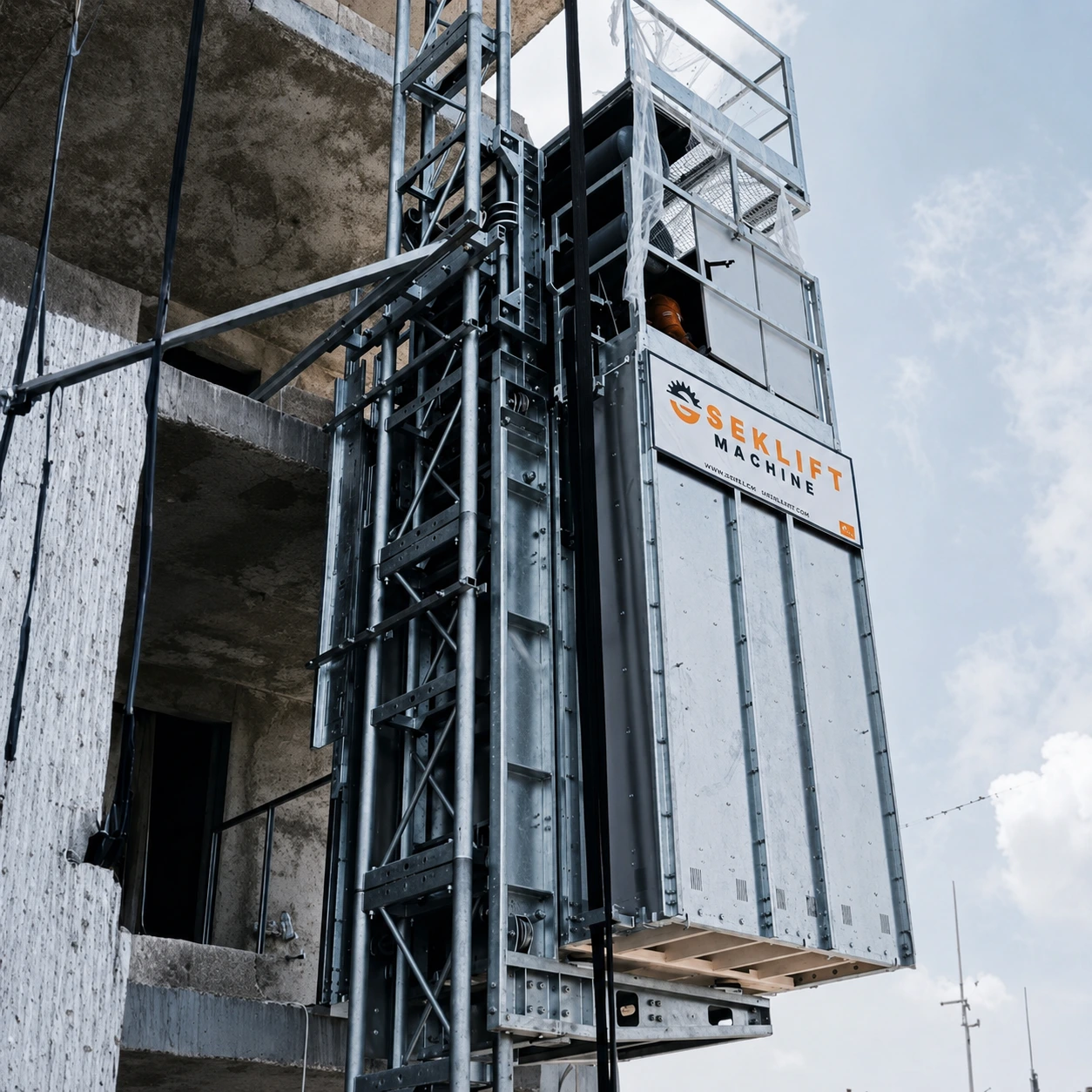 Mining Elevator Systems
Монтаж шахтного подъемника SEKLIFT для вертикального перемещения на горнодобывающем участке.
Mine-hoist rope standards and regulations define different parts of the decision framework
Стандарты на продукцию, методы испытаний, руководства регуляторов и обязательные правила для шахт выполняют разные задачи. Стандарты на продукцию определяют требования к поставке канатов определенных конструкций. Стандарты на испытания определяют порядок измерения свойств. Горное законодательство, утвержденные правила и эксплуатационные разрешения регламентируют монтаж, осмотр, испытания и вывод из эксплуатации. Публикация стандарта не означает его юридическую применимость в каждой стране, а сертификат продукции не свидетельствует о текущем состоянии каната.
International and European standards
The ISO catalogue listed ISO 3154:1988, ISO 3155:1976, ISO 3156:1976 and ISO 5614:1988 as published/current documents when checked, while also showing review or revision activity for these older editions. ISO 3108:2017 remained the current test method for determining measured breaking force. ISO 4309:2017 remained published but was marked for revision, with successor work under development. Users should therefore verify the edition required by contract or law at the time of application. Standards status checked 3 September 2026.
- ISO 3154:1988 — technical delivery requirements for stranded mine-hoisting ropes within its stated scope.
- ISO 5614:1988 — technical delivery requirements for locked-coil mine-hoisting ropes.
- ISO 3155:1976 — characteristics and tests for fibre components used in stranded mine-hoisting ropes.
- ISO 3156:1976 — characteristics and tests for impregnating compounds, lubricants and service dressings.
- ISO 3108:2017 — tensile test method for determining measured breaking force.
- ISO 4309:2017 — care, maintenance, inspection and discard guidance for ropes on cranes, winches and hoists; supplementary for mine applications only when invoked by the applicable framework.
BSI listed BS EN 12385-1:2002+A1:2008, BS EN 12385-2:2002+A1:2008, BS EN 12385-6:2004 and BS EN 12385-7:2002 as current and under review when checked. Part 1 supplies general manufacturing and testing requirements; Part 2 defines terminology, designation and classification. Part 6 gives particular requirements for stranded and flat ropes for mine shafts and is used with Parts 1 and 2. Part 7 specifies additional materials, manufacturing and testing requirements for full-locked-coil hoist ropes and half- or full-locked-coil guide ropes for mine shafts to those given in Part 1, within the broader EN 12385 series framework. These are product standards, not universal in-service discard rules. (BSI: Part 1; Part 2; Part 6; Part 7)
United States: mine category and equipment scope matter
The earlier shorthand “U.S. metal/nonmetal provisions” is insufficient. Current federal rules use parallel but category-specific sections:
- 30 CFR Part 56 applies to surface metal and nonmetal mines.
- 30 CFR Part 57 applies to underground metal and nonmetal mines.
- 30 CFR Part 75 applies to underground coal mines.
- 30 CFR Part 77 applies to surface coal mines and surface work areas of underground coal mines.
Within the cited hoisting-rope provisions, §§56.19023, 57.19023, 75.1433 and 77.1433 require visual examination of the active rope length at least every 14 calendar days and, at least every six months, either nondestructive testing of the active length or prescribed diameter measurements at wear-prone locations. Daily examination applies to an affected portion when a visible condition may reduce strength. The corresponding removal sections—§§56.19024, 57.19024, 75.1434 and 77.1434—include diameter reduction due to wear exceeding 6% of the baseline diameter measurement and more than 10% rope-strength loss as determined by NDT, alongside broken-wire, corrosion, distortion and heat-damage criteria. The baseline is established after initial stretch but before visible wear under §§56.19022, 57.19022, 75.1432 and 77.1432. (30 CFR Parts 56 and 57; Parts 75 and 77)
Those percentages are U.S. regulatory removal criteria for ropes within the stated scope—not global material-failure thresholds. The Part 57 application provision and the cited Part 75 and Part 77 scope provisions expressly exclude wire ropes used for elevators; the detailed installation must therefore be classified correctly before any section is applied. They must not be transferred automatically to a mining elevator, a Turkish project or another jurisdiction.
United Kingdom, New South Wales and Türkiye
UK HSE's Steel wire ropes in vertical mine shafts is guidance for people who manufacture, select, install, inspect, examine or maintain winding, balance, guide and rubbing ropes. Its technical annexes address maintenance, deterioration and discard. It is authoritative guidance, not a universal statute or a substitute for current UK legal duties. (HSE)
The NSW Code of Practice: Mine shafts and winding systems, Version 2, April 2026, is an approved code of practice under section 274 of the NSW Work Health and Safety Act 2011. It guides principal-hazard management for underground mine shafts and winding systems, including lifecycle controls and ropes. It is admissible in proceedings and can evidence what is known about a hazard or control; it is not itself an exhaustive statement of the law, and equivalent or higher-standard methods may be used where the WHS framework permits. (NSW Resources Regulator, 2026)
This review did not establish, from an accessible authoritative source, a single Turkish mine-hoisting-rope regime that could be summarized safely across mine type and equipment category. The Turkish Koepe-rope field study cited above is research evidence, not legislation. Projects in Türkiye should verify current Turkish mining and occupational-safety legislation, applicable adopted TS EN standards, mine approvals and equipment classification with the competent authority and responsible engineer rather than importing U.S., UK or NSW thresholds.
For a real project, the controlling hierarchy normally begins with:
- Applicable mining and occupational-safety law and regulator requirements.
- Mine approvals, the winding-system safety case or principal-hazard plan, and applicable approved codes.
- Rope and winder manufacturers' instructions for the approved configuration.
- Applicable mine-rope product and test standards.
- General wire-rope guidance used only where the governing framework invokes or permits it.
Treat the rope as a monitored mechanical system
Mine-hoist wire-rope failure is best understood as a sequence, not a label. Dynamic loading, bending, torsion, contact geometry, lubrication and environment can initiate abrasive or adhesive wear, fretting, fatigue cracks, corrosion pits, internal breaks or localized metallic-area loss. As damage develops, load sharing changes. The remaining wires may ultimately fracture in ductile overload even when progressive deterioration began the loss of capacity.
That model does not make every failure progressive or identical. It explains why root cause cannot be read from one final fracture surface, one diameter value, one NDT trace, calendar age or nominal breaking force. Each indicator answers only part of the condition question.
For mine engineers and procurement teams, the practical implication is systems-based specification and evidence: match rope construction and grade to the winder and duty; verify product conformity; control installation twist and lubrication; preserve baseline measurements; trend location-specific visual and NDT findings; and apply the correct jurisdiction's examination and removal rules. Replacement decisions must remain project-specific and should be made by the competent mine or winding-system engineer under the applicable legal and approved technical framework.
Explore mine-site vertical access equipment for personnel, tools and material movement.
View mining elevators →Peer-reviewed literature
- Wang, D., Zhang, D. and Ge, S. 2013. “Determination of fretting parameters of hoisting rope in coalmine and fretting-fatigue behavior of steel wires.” Industrial Lubrication and Tribology, 65(6), 436–448. https://doi.org/10.1108/ILT-03-2011-0021
- Wang, D., Zhang, D., Zhang, Z. and Ge, S. 2012. “Effect of various kinematic parameters of mine hoist on fretting parameters of hoisting rope and a new fretting fatigue test apparatus of steel wires.” Engineering Failure Analysis, 22, 92–112. https://doi.org/10.1016/j.engfailanal.2012.01.008
- Peng, Y., Huang, K., Ma, C., Zhu, Z., Chang, X., Lu, H., Zhang, Q. and Xu, C. 2023. “Friction and wear of multiple steel wires in a wire rope.” Friction, 11(5), 763–784. https://doi.org/10.1007/s40544-022-0665-y
- Huang, K., Li, G., Chang, X., Zhou, Z., Peng, Y. and Deng, R. 2025. “Fretting friction and wear characteristics of the internal spiral contact steel wires in the hoisting wire rope under different service conditions.” Lubricants, 13(10), 453. https://doi.org/10.3390/lubricants13100453
- Wang, S., Zhang, D., Hu, N. and Zhang, J. 2016. “Effect of stress ratio and loading frequency on the corrosion fatigue behavior of smooth steel wire in different solutions.” Materials, 9(9), 750. https://doi.org/10.3390/ma9090750
- Wang, D., Zhu, Z. and Song, D. 2020. “Effects of tensile stress ratio and amplitude on tension-torsion fretting-corrosion-fatigue behaviors of non-perpendicularly crossed steel wires.” Engineering Failure Analysis, 117, 104839. https://doi.org/10.1016/j.engfailanal.2020.104839
- Singh, R. P., Mallick, M. and Verma, M. K. 2016. “Studies on failure behaviour of wire rope used in underground coal mines.” Engineering Failure Analysis, 70, 290–304. https://doi.org/10.1016/j.engfailanal.2016.09.002
- Schrems, K. K. 1994. “Wear-related fatigue in a wire rope failure.” Journal of Testing and Evaluation, 22(5), 490–499. https://doi.org/10.1520/JTE12670J
- Chang, X., Peng, Y., Zhu, Z., Gong, X., Yu, Z., Mi, Z. and Xu, C. 2019. “Breaking failure analysis and finite element simulation of wear-out winding hoist wire rope.” Engineering Failure Analysis, 95, 1–17. https://doi.org/10.1016/j.engfailanal.2018.08.027
- Chang, X., Shi, F., Chen, X., Peng, Y., Tang, Y., Xiao, W. and Hu, R. 2025. “Mechanical property degradation of transmission wire rope caused by different wear evolution.” Lubricants, 13(2), 59. https://doi.org/10.3390/lubricants13020059
- Zhang, D., Chen, K., Jia, X., Wang, D., Wang, S., Luo, Y. and Ge, S. 2013. “Bending fatigue behaviour of bearing ropes working around pulleys of different materials.” Engineering Failure Analysis, 33, 37–47. https://doi.org/10.1016/j.engfailanal.2013.04.018
- Zhang, D., Feng, C., Chen, K., Wang, D. and Ni, X. 2017. “Effect of broken wire on bending fatigue characteristics of wire ropes.” International Journal of Fatigue, 103, 456–465. https://doi.org/10.1016/j.ijfatigue.2017.06.024
- Onur, Y. A. 2012. “Condition monitoring of Koepe winder ropes by electromagnetic non-destructive inspection.” Insight—Non-Destructive Testing and Condition Monitoring, 54(3), 144–148. https://doi.org/10.1784/insi.2012.54.3.144
- Tytko, A., Olszyna, G., Rokita, T. and Skrzypkowski, K. 2025. “Strength tests of selected ropes used in mining shaft hoists after their replacement in stochastic interpretation.” Materials, 18(17), 4217. https://doi.org/10.3390/ma18174217
- Peterka, P., Krešák, J., Kropuch, S., Fedorko, G., Molnar, V. and Vojtko, M. 2014. “Failure analysis of hoisting steel wire rope.” Engineering Failure Analysis, 45, 96–105. https://doi.org/10.1016/j.engfailanal.2014.06.005
- Hu, Z., Wang, E., Jia, F. and Dong, M. 2023. “Experimental study on effect of additional torsional load on bending fatigue behavior and failure mechanism of steel wire rope.” International Journal of Fatigue, 167, 107399. https://doi.org/10.1016/j.ijfatigue.2022.107399
Standards and regulatory sources
- International Organization for Standardization (ISO). ISO 3154:1988, Stranded wire ropes for mine hoisting—Technical delivery requirements. Status checked 3 September 2026: Published; current edition; review stage 90.60. ISO
- International Organization for Standardization (ISO). ISO 3155:1976, Stranded wire ropes for mine hoisting—Fibre components—Characteristics and tests. Status checked 3 September 2026: Published; current edition; review stage 90.60. ISO
- International Organization for Standardization (ISO). ISO 3156:1976, Stranded wire ropes for mine hoisting—Impregnating compounds, lubricants and service dressings—Characteristics and tests. Status checked 3 September 2026: Published; review stage 90.60. ISO
- International Organization for Standardization (ISO). ISO 3108:2017, Steel wire ropes—Test method—Determination of measured breaking force. Status checked 3 September 2026: Published; confirmed in 2023 and current. ISO
- International Organization for Standardization (ISO). ISO 4309:2017, Cranes—Wire ropes—Care and maintenance, inspection and discard. Status checked 3 September 2026: Published/current; marked “to be revised” at stage 90.92, with ISO/CD 4309 under development. ISO
- International Organization for Standardization (ISO). ISO 5614:1988, Locked coil wire ropes for mine hoisting—Technical delivery requirements. Status checked 3 September 2026: Published; review stage 90.60. ISO
- British Standards Institution (BSI) / European Committee for Standardization (CEN). BS EN 12385-1:2002+A1:2008, Steel wire ropes—Safety—Part 1: General requirements. Status checked 3 September 2026: Current, under review. BSI
- British Standards Institution (BSI) / European Committee for Standardization (CEN). BS EN 12385-2:2002+A1:2008, Steel wire ropes—Safety—Part 2: Definitions, designation and classification. Status checked 3 September 2026: Current, under review. BSI
- British Standards Institution (BSI) / European Committee for Standardization (CEN). BS EN 12385-6:2004, Steel wire ropes—Safety—Part 6: Stranded ropes for mine shafts. Status checked 3 September 2026: Current, under review; used in conjunction with Parts 1 and 2. BSI
- British Standards Institution (BSI) / European Committee for Standardization (CEN). BS EN 12385-7:2002, Steel wire ropes—Safety—Part 7: Locked coil ropes for mine shafts. Status checked 3 September 2026: Current, under review; specifies additional mine-shaft locked-coil requirements to those given in Part 1, within the broader EN 12385 series framework. BSI
- Mine Safety and Health Administration (MSHA). 30 CFR Part 56, surface metal/nonmetal mines, Subpart R—Personnel Hoisting. Current eCFR text checked 3 September 2026. eCFR
- Mine Safety and Health Administration (MSHA). 30 CFR Part 57, underground metal/nonmetal mines, Subpart R—Personnel Hoisting. Current eCFR text checked 3 September 2026. eCFR
- Mine Safety and Health Administration (MSHA). 30 CFR Part 75, underground coal mines, §§75.1430–75.1434. Current eCFR text checked 3 September 2026. eCFR
- Mine Safety and Health Administration (MSHA). 30 CFR Part 77, surface coal mines and surface work areas of underground coal mines, §§77.1430–77.1434. Current eCFR text checked 3 September 2026. eCFR
- Mine Safety and Health Administration (MSHA). Program Information Bulletin P09-10, Non-Destructive Testing of Mine Hoist Ropes. Official MSHA source. MSHA
- UK Health and Safety Executive (HSE). Guidance on the selection, installation, maintenance and use of steel wire ropes in vertical mine shafts. Guidance; current HSE guidance page checked 3 September 2026. HSE
- NSW Resources Regulator. 2026. NSW Code of Practice: Mine shafts and winding systems, Version 2, April 2026. Approved code of practice under section 274 of the Work Health and Safety Act 2011. Official PDF
Standards and regulatory status checked 3 September 2026. Applicable editions, national adoptions and legal requirements must be verified for each project.