Industrial & Freight Elevators Permanent Personnel & Goods Access
SEKLIFT manufactures industrial elevators and develops project-specific freight elevator solutions for permanent access in factories, warehouses and other industrial facilities. The SM-GTP-102 is the model-based rack-and-pinion option; hydraulic and special freight systems follow a custom engineering route. Terms such as freight lift, goods lift and cargo lift describe buyer requirements, not interchangeable approvals. Define what is transported, whether personnel travel is required, the load dimensions, travel and stops before selecting the system.
- 01Cement Plants
- 02Factories
- 03Silos & Towers
- 04Power Facilities
- 05Warehouses
Freight elevator, freight lift and goods lift: specify the duty
These terms commonly describe vertical goods transport, but permitted users, entrances and operating arrangements depend on the actual system and destination-market requirements. Do not infer passenger permission from “freight elevator” or “goods lift.” An industrial elevator describes the facility application; the intended personnel, freight or combined duty must still be confirmed.
Model-based or custom industrial access?
Review the SM-GTP-102 rack-and-pinion model first where a mast-based permanent installation fits. Compare the existing hydraulic and special-freight options below if load geometry, entrances or facility interfaces require a custom solution. Published SM-GTP-102 values are not specifications for the custom systems, and selectable speeds are not simultaneous operating values.
What should a procurement package include?
Request a configuration-specific technical sheet, cage and door drawing, base and tie reactions, landing interfaces, electrical requirements, operating and inspection instructions, and the applicable conformity documents. Use the industrial-elevator evidence and project-input checklist before sending your industrial elevator requirements. Supply the payload and largest load dimensions, intended users, travel, stops, duty cycle, site conditions and country.
Industrial Elevator Manufacturer Turkey. One Core Model + Two Project-Engineered Paths.
Industrial Elevator Manufacturer
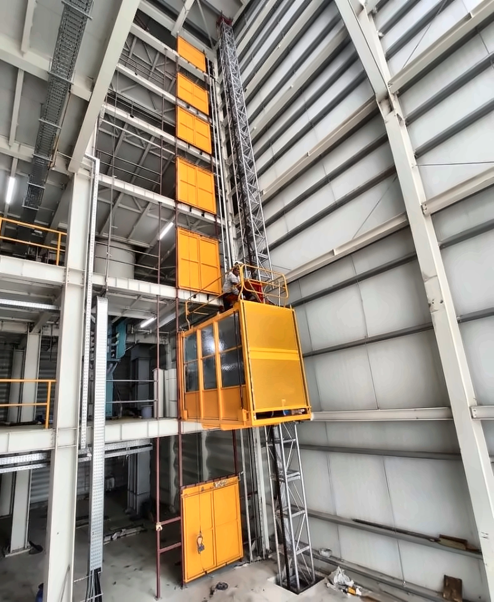
The SM-GTP-102 freight and personnel elevator is the primary system in the SEKLIFT industrial range, combining a 2,500 kg rated load, capacity for 23 persons, selectable lifting speeds, and travel up to 200 m. Hydraulic and special freight elevators are developed as custom systems around the building interface, transported load, access geometry, and operating duty.
Verified figures are shown only for SM-GTP-102.RACK-AND-PINION FREIGHT & PERSONNEL ELEVATOR
SEKLIFT SM-GTP-102 Industrial Elevator
The SM-GTP-102 combines a large 3,000 × 1,500 mm cage with a wide side opening for bulky materials, selectable 36, 54, or 90 m/min lifting speed, and a mast system engineered for vertical travel up to 200 m. Higher mast heights can be evaluated upon request.
The 2.6 m side-door opening supports the movement of large materials, while front and rear doors allow the landing flow to be planned around the building.
Personnel and Freight Elevator Access Geometry
The cage and door arrangement gives specifiers exact working dimensions before landing and building interfaces are finalized.
A defined rack-and-pinion mast platform
Verified mast geometry, rack module, fastening class, and component weights support early site coordination.
- Square mast section
- 550 × 550 mm
- Mast section height
- 1,500 mm
- Rack module
- 6 mm
- Mounting bolts
- M24 × 260 / 10.9
- Mast weight / single rack
- 133 kg
- Mast weight / double rack
- 149 kg
- Top drive unit weight
- 450 kg
Choose cycle performance around the facility
The SM-GTP-102 offers three lifting-speed choices. Supplied motor, starting-current, and maximum-consumption figures are shown below for the 36 and 54 m/min versions.
| Configuration | 36 m/min | 54 m/min |
|---|---|---|
| Hoisting motors | 2 × 9.2 kW | 3 × 7.5 kW |
| Maximum starting current | 120 A | 150 A |
| Maximum power consumption | 33 kW | 40 kW |
- Supply voltage
- 400 V / 50 Hz
- Control voltage
- 48 V / 50 Hz / 24 V DC
- 90 m/min option
- Electrical package confirmed for the final configuration
Protection across movement, access, and emergency conditions
The stated SM-GTP-102 safety package combines mechanical protection, monitored operating limits, controlled access, and emergency-response systems.
Specified as the model's mechanical safety-brake unit.
Included in the stated equipment for emergency lowering.
Upper and lower mast-mounted limit switches are included.
Specified to detect loading beyond the configured limit.
A dedicated locking device is specified for the cage door.
The stated braking package uses spring-loaded disc brakes.
Emergency-stop provisions are included in the safety package.
The stated safety guardrail height is 1.10 m.
Coordinate the base before site installation
When the Facility Defines the Elevator
The following systems are custom-made rather than fixed catalog configurations. Their capacity, travel, cage or platform dimensions, entrances, drive package, and controls are defined only after the real project conditions are reviewed.
PROJECT-ENGINEERED HYDRAULIC INDUSTRIAL ELEVATOR
Custom Hydraulic Elevator
A hydraulic elevator is developed around the actual facility rather than forced into a preset catalog envelope. The engineering brief aligns the transported load, travel and stops, usable platform or cage size, entrance arrangement, structural space, operating cycle, and control requirements.
PROJECT-ENGINEERED INDUSTRIAL FREIGHT ELEVATOR
Freight Elevator — Project-Engineered Special Configuration
Built for loads and workflows that a standard elevator cannot describe properly. The final system is shaped around the goods, their handling method, loading interface, cage or platform envelope, door geometry, landing arrangement, travel, operating frequency, and industrial environment.
Industrial Elevators. Start with the System, Finish Around the Project.
Begin here when the 2,500 kg / 23-person platform, stated cage geometry, selectable speed range, and mast system align with the required duty.
Review SM-GTP-102 specifications ↑Choose a project engineering review when the hydraulic arrangement, structural envelope, stops, doors, and operating cycle must be defined together.
Review hydraulic planning inputs ↑Use this path when load geometry, material-handling method, access openings, or the industrial workflow requires a purpose-built freight system.
Review freight planning inputs ↑Rack-and-pinion vs hydraulic industrial elevator: when to consider each
Neither system is universally better. Start with transport duty, travel, structure, landing access, load geometry and site conditions, then confirm the final configuration through project-specific engineering review.
| Decision factor | Rack-and-pinion industrial elevator | Hydraulic freight / industrial lift |
|---|---|---|
| Typical application | Permanent personnel and freight access where the SM-GTP-102 mast-based platform aligns with the facility. | A custom freight or industrial system defined around the facility and lifting duty. |
| When to consider | The published SM-GTP-102 load, cage, travel and speed options fit, and the mast, base, anchoring and landing interfaces can be coordinated. | The facility requires a custom load platform or cage, entrance arrangement, travel, stops, structural envelope or controls. |
| Published reference | SM-GTP-102: 2,500 kg rated load, 23 persons, travel up to 200 m, and selectable 36 / 54 / 90 m/min speed. | Project-specific review required. |
| Installation interface | 550 × 550 mm mast section; base, anchoring and landing interfaces require project review. | Shaft, pit, headroom and structural interfaces: project-specific review required. |
| Load and access geometry | Published 3,000 × 1,500 × 2,000 mm cage, front and rear doors, plus a 2,600 mm-wide side opening. | Capacity, platform or cage dimensions, entrances and openings are defined after project review. |
| Duty pattern | Permanent movement of personnel, tools and freight; cycle performance is confirmed for the actual facility. | Project-specific review required for operating duty and cycle requirements. |
| Machine room and pit | Project-specific review required. | Project-specific review required. |
| Environment | Power supply, site conditions and operating environment must be reviewed. | Project-specific review required. |
| Maintenance planning | Inspection, access and service planning are confirmed for the installed configuration. | Inspection, access and service planning are confirmed for the engineered system. |
| Customization path | Model-based speed, drive and project configuration choices around the SM-GTP-102 platform. | Capacity, travel, dimensions, entrances, drive and controls are defined after engineering review. |
Next step: use the guide for classification context, then share the required payload, load dimensions, travel, landing count, door arrangement, structural envelope, duty cycle, power supply and site conditions.
Define the industrial elevator around the work it must do.
A useful engineering review starts with the real operating conditions—not a generic product label. Share the project constraints below so SEKLIFT can evaluate the SM-GTP-102, a hydraulic arrangement, or a purpose-built freight solution.
- 01 Load & duty Material, personnel and operating cycle
- 02 Travel & access Height, landings, doors and openings
- 03 Site envelope Cage size, power and available space
