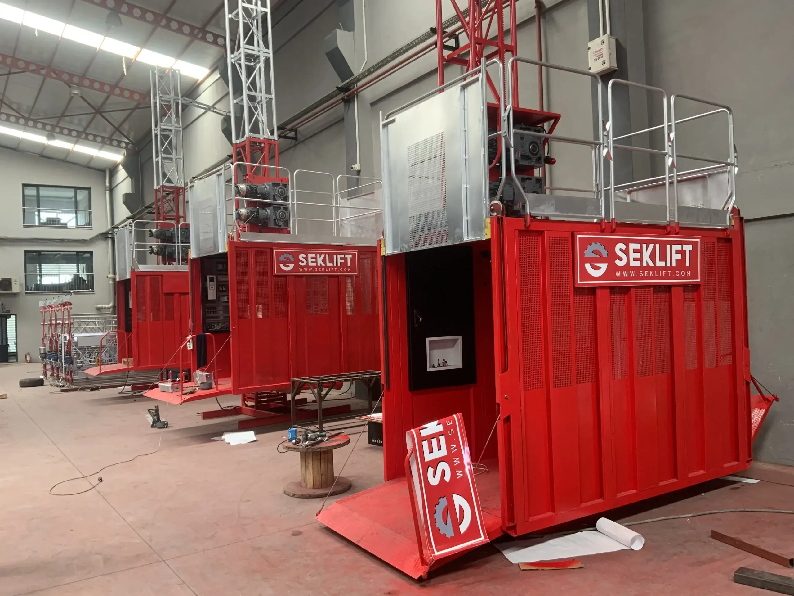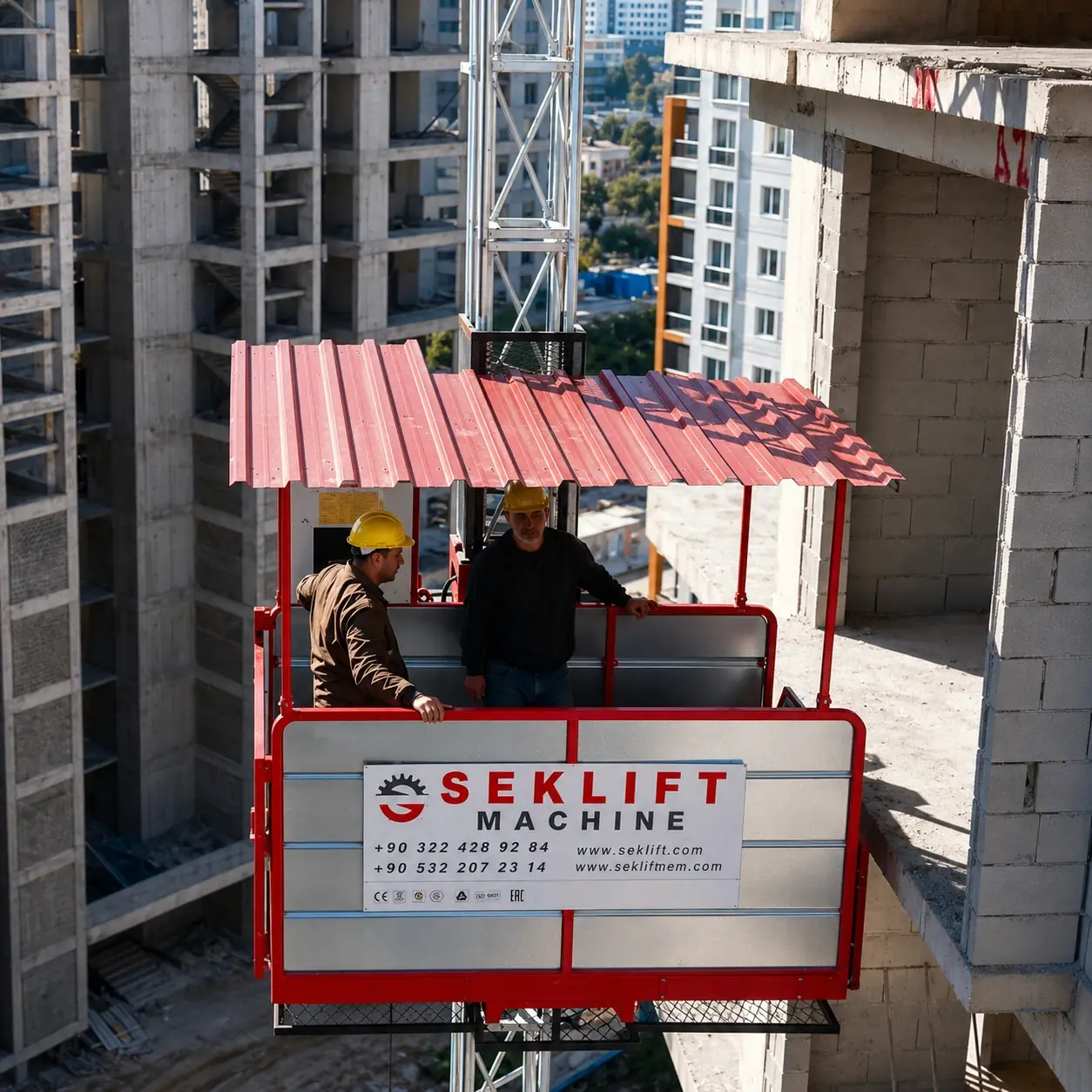
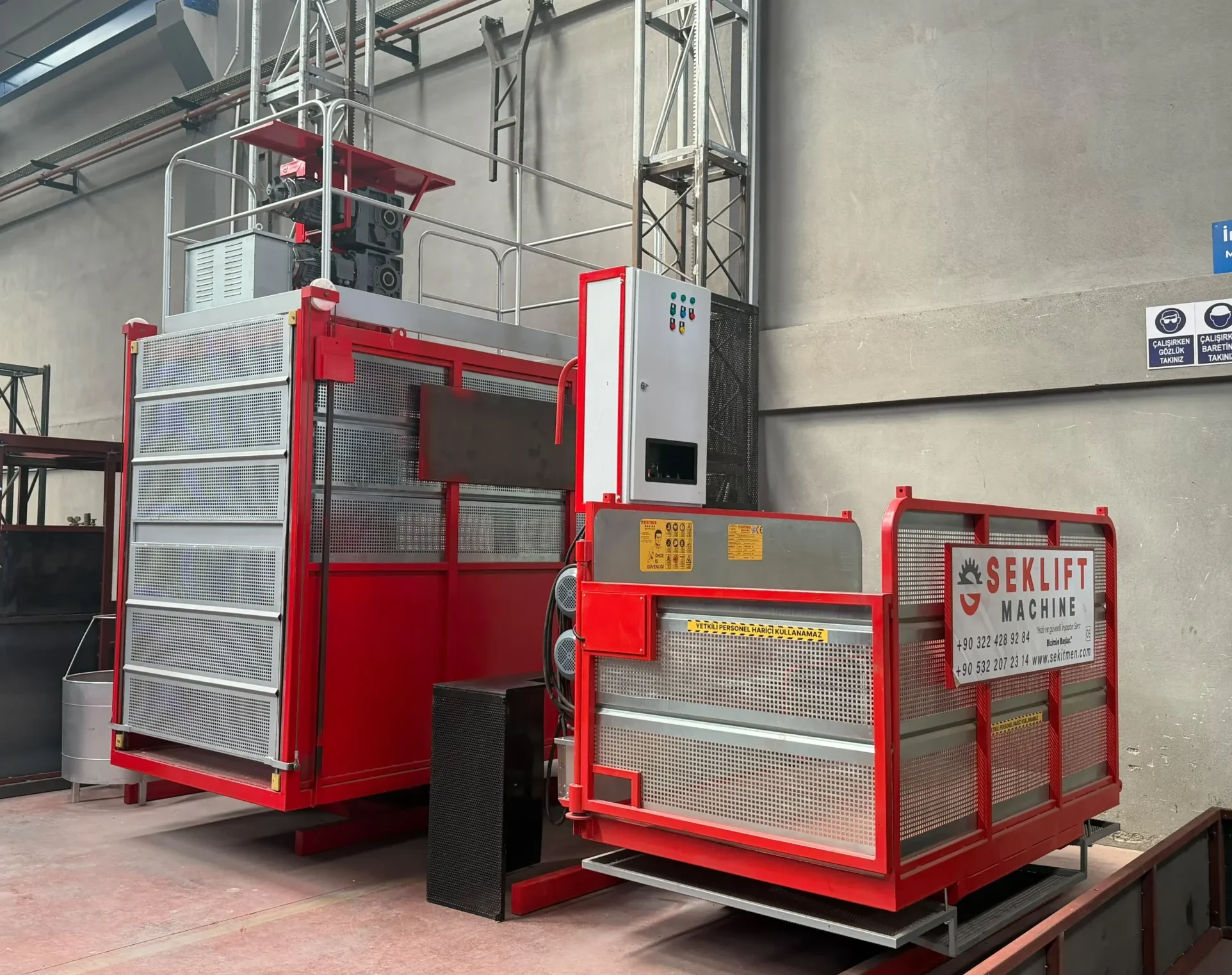
A construction hoist carries people and heavy loads on a temporary structure, in the open air, on a site that changes every week. That’s a demanding job. European design rules (EN 12159, under the Machinery Directive) therefore expect several independent layers of protection: one system prevents the dangerous situation, and another limits the consequences if the first one fails.
This article is about the machine: the devices engineered into the hoist. For the people side (safe boarding, landing gates, loading and what to do in an emergency), read Where do you board and exit a construction hoist?
It explains the nine safety systems fitted as standard to our SM-GTP-101 Personnel & Material Hoist. For each one we cover the hazard it addresses, how it works, and what site teams should check. The list is a useful benchmark for any hoist you’re comparing.
Quick reference: the 9 standard systems
01 Overspeed safety gear · 02 Overload protection · 03 Door interlocks · 04 Limit & final limit switches · 05 Mechanical locks · 06 Buffer springs · 07 Emergency lowering · 08 Roof-hatch interlock · 09 E-stops & roof guardrail
How the layers work together
| Hazard | Prevent (first layer) | Protect (second layer) |
|---|---|---|
| Cage falls or overspeeds | Twin motors, each with its own spring-applied brake | 01 Overspeed safety gear |
| Overloading | 02 Overload sensor blocks travel | Structural safety margins in design |
| People caught by a moving cage | 03 Door interlocks, ground enclosure | 09 Emergency stops |
| Cage overruns the top or bottom | 04 Limit switches | 04 Independent final limit, 06 buffers, mast top section |
| Cage leaves the mast / pinion jumps the rack | Guide and pressure rollers | 05 Mechanical locks |
| Power failure with people aboard | Brakes hold the cage | 07 Manual emergency lowering |
| Work on the cage roof | 08 Hatch interlock | 09 Roof E-stop and guardrail |
01 Overspeed safety gear (the “parachute”)
Hazard: uncontrolled descent after a failure in the drive train (gearbox, shaft, coupling) or the brakes.
How it works: the safety gear is a self-contained arresting device mounted on the drive unit, with its own pinion running on the mast rack, independent of the drive pinions. When the cage’s downward speed exceeds the device’s tripping limit, it locks and brings the cage to a controlled stop on the mast. An integrated monitoring switch cuts drive power at the same moment, so the motors can’t fight the device.
What to check: the safety gear is a type-tested safety component. It’s sealed, and it must be tested and replaced at the intervals given by the manufacturer and by local regulations. Many countries require a periodic safety-gear test (often called a drop test) by a competent person. See our guides for Germany, Türkiye and Brazil (NR-18). Never adjust or open the device on site.
02 Overload protection
Hazard: overloading the cage stresses the drive, brakes, rack, mast and ties beyond their design margin. It’s one of the most common misuse scenarios on site.
How it works: a load-pin sensor in the cage suspension measures the load continuously. Above the rated load (2,000 kg on the SM-GTP-101), an audible alarm sounds and travel is blocked until the excess load is removed. An optional load measuring & display system shows the actual load to the operator.
What to check: the alarm and cut-off should be function-tested with a known test load at commissioning and at every periodic inspection. Spread loads evenly over the cage floor, and never let loads protrude through doors.
03 Door interlocks
Hazard: someone falling from a landing or the cage, or being struck by a moving cage.
How it works: every cage door and the ground-enclosure door has an electrical interlock switch. The cage can’t move unless all doors are closed and confirmed. At ground level, the enclosure door is also mechanically interlocked, so it can only open when the cage is at the bottom landing.
What to check: test each door daily. The cage must not respond to the controls with any door open. Landing gates at upper floors need the same discipline: they belong to the installation and must stay closed when the cage isn’t there.
04 Limit and final limit switches
Hazard: the cage overrunning the top of the mast or striking the base.
How it works: operational limit switches stop the cage automatically at the top and bottom of its working travel. An independent final limit switch, actuated separately, cuts the power if the normal limit fails. A top section on the mast provides extra physical safety above the highest stop.
What to check: after every mast extension, re-position the top limit cam and test the final limit before the hoist goes back into service. A mast that grows faster than its limit settings is a classic cause of incidents.
05 Mechanical locks
Hazard: the cage leaving the mast, or the drive pinions disengaging from the rack, for example after a roller failure.
How it works: mechanical retaining devices on the drive unit physically prevent the cage from coming off the mast and keep the pinions in mesh, even if a guide or pressure roller fails.
06 Buffer springs
Hazard: impact at the bottom landing if the cage overruns the lower limit.
How it works: buffers on the base frame absorb the cage’s energy and decelerate it.
What to check: the buffers are inside the ground enclosure, a zone that must stay clear of materials and debris. Inspect them for damage and ageing.
07 Emergency lowering
Hazard: people trapped in a stationary cage between floors after a power failure.
How it works: the spring-applied brakes hold the cage whenever power is lost. A manual brake release lets a trained person lift the brakes in a controlled way, so the cage descends to the next landing. The speed is still supervised by the overspeed safety gear.
What to check: brief the operators and keep the rescue procedure posted. Passengers should never try to leave a stopped cage between landings. See the emergency section of our boarding and landing safety guide.
08 Roof-hatch interlock
Hazard: a person on the cage roof (during erection, inspection or emergency escape) being exposed while the cage moves under normal control.
How it works: opening the escape hatch cuts motor power. The hoist can’t be driven normally from inside the cage while someone may be on the roof.
09 Emergency stops and roof guardrail
Hazard: any situation that needs the machine stopped immediately.
How it works: E-stop buttons in the cage and on the roof control station stop all motion. They’re designed to EN ISO 13850 (emergency stop function). A guardrail around the cage roof protects erection and service crews working at height.
Standards behind these devices
| Standard | What it covers, in short |
|---|---|
| EN 12159 | Product standard for builders’ hoists for persons and materials with vertically guided cages |
| EN ISO 12100 | Risk assessment and risk reduction method used to identify the hazards above |
| EN ISO 13849-1 | Design of safety-related parts of control systems (interlocks, limits, overload cut-off) |
| EN ISO 13850 | Emergency stop function |
| EN ISO 13854 | Minimum gaps to avoid crushing of body parts |
| EN ISO 14120 | Fixed and movable guards (enclosure, cage panels) |
| EN 60204-1 / EN 60204-32 | Electrical equipment of machines, general and hoisting-machine-specific |
Read the full explanation in our EN 12159 guide.
A daily pre-use check every operator can do
These operator checks don’t replace the manufacturer’s maintenance schedule or statutory inspections:
- Walk the ground enclosure: clear of material, buffers intact, door interlock working.
- Check that every cage door stops the hoist when opened.
- Test both E-stops.
- Run one empty trip to the top and back: listen for unusual noise from rack, pinions or rollers, and confirm the top and bottom limits stop the cage.
- Check the trailing cable is running cleanly in its guides.
- Check the wind at cage height is below the in-service limit (72 km/h for the SM-GTP-101). See wind speed limits.
- Report any fault and take the hoist out of service until a competent person clears it.
Frequently asked questions
What is the safety gear on a construction hoist?
It’s an independent, overspeed-triggered arresting device with its own pinion on the mast rack. If the cage descends faster than its tripping limit, it locks onto the rack, stops the cage and cuts drive power.
Can a construction hoist fall if the motor brake fails?
A properly maintained hoist has two independent protections. Each motor has its own spring-applied brake, and the overspeed safety gear stops the cage if the drive or brakes fail.
What happens when a construction hoist is overloaded?
On the SM-GTP-101, a load-pin sensor detects the overload, an alarm sounds, and travel is blocked until the excess load is removed.
Why can’t the cage move with the door open?
Every cage and ground-enclosure door is fitted with an interlock in the safety control circuit. Travel is only enabled when all doors are confirmed closed.
How do you get people out of a hoist during a power cut?
The brakes hold the cage automatically. A trained person uses the manual brake release to lower it, under the supervision of the safety gear, to the next landing, where passengers exit normally.
Ask every supplier for the same list: which of these nine systems are standard, which are options, and which standards they’re designed to. You’ll find the complete standard safety specification for the SM-GTP-101 on its technical data sheet (PDF).
Request a technical proposal →Sources
- SEKLIFT, SM-GTP-101 Technical Data Sheet, DS-SM-GTP-101 Rev. 2, 10.2026: safety equipment and compliance sections.
- ISO, ISO 13850:2015 Safety of machinery — Emergency stop function — Principles for design.
- ISO, ISO 14120:2015 Safety of machinery — Guards.
- ISO, ISO 13849-1:2023 Safety-related parts of control systems.
- US OSHA, 29 CFR 1926.552 Material hoists, personnel hoists, and elevators (for comparison with US practice).