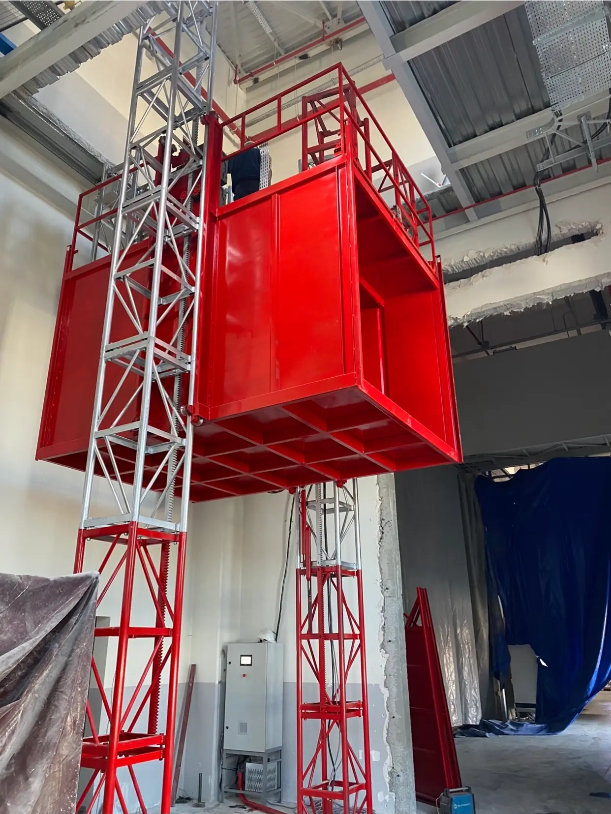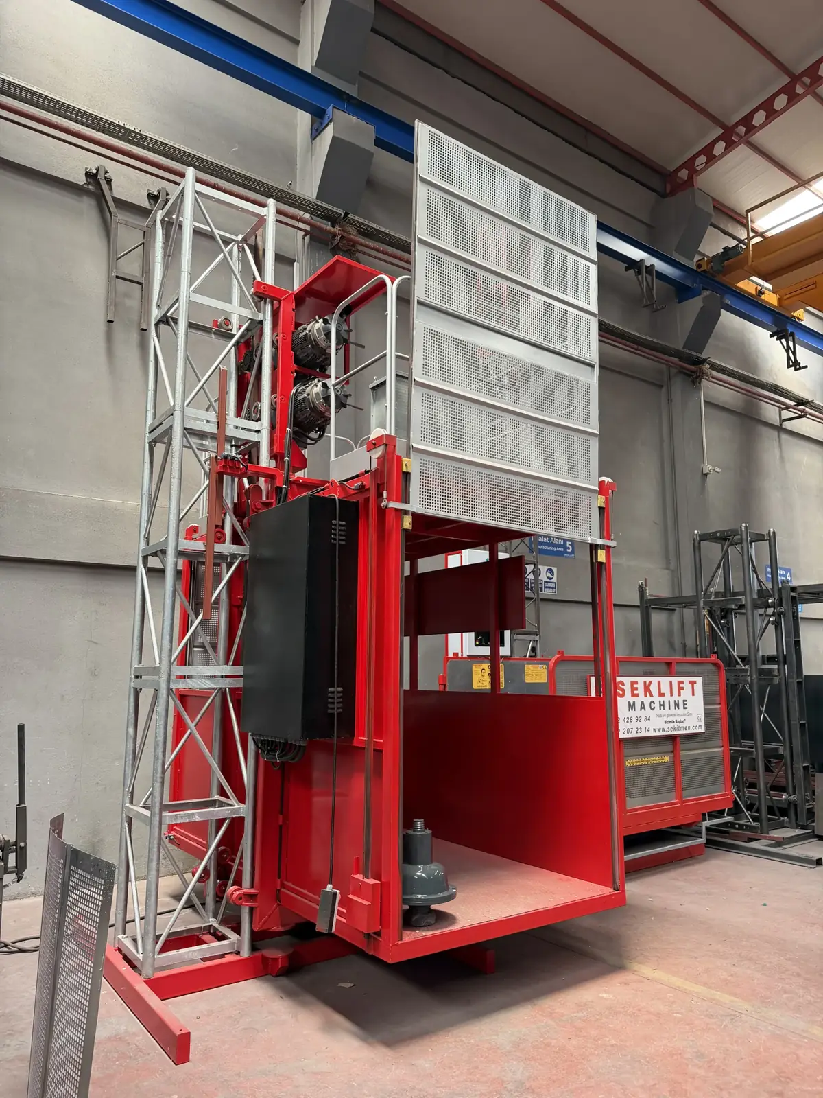
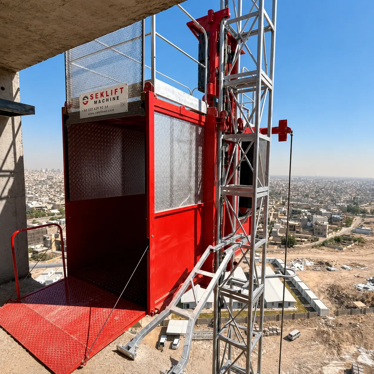
A rack-and-pinion construction hoist (also called a builders’ hoist, or a personnel and material hoist) moves a cage up a vertical steel mast. Motors on the cage turn pinion gears, and the pinions mesh with a gear rack fixed to the mast. There are no ropes, no counterweight and no machine room. That’s why the mast can grow floor by floor with the building, and why the same machine can serve a 30 m apartment block or a 150 m tower.
If you’re still choosing between hoist types (passenger/material, material-only, transport platforms, single or twin cage), start with our practical guide to construction hoist types. This guide goes one level deeper: it explains each subsystem of a rack-and-pinion hoist and what it does. We use the published data of our SM-GTP-101 Personnel & Material Hoist as a worked example, so every number below can be checked against a real data sheet.
Key figures: SM-GTP-101 (standard configuration)
Rated load 2,000 kg · Travel speed 40 m/min (0.67 m/s) · Drive 2 × 7.5 kW twin motor · Mast module 1.5 m · Cage internal 1.45 × 2.80 × 2.20 m · Supply 3-phase 380–400 V, 50 Hz
The principle in one paragraph
The cage is bolted to a drive unit (also called the climbing unit or carrier). Geared motors on the drive unit turn pinions. The pinions engage a gear rack that runs the full height of the mast. When the motors turn, the pinions “walk” up or down the rack and carry the cage with them. Guide rollers running on the mast chords keep the cage aligned. Pressure rollers hold the pinions in correct mesh with the rack. When the motors stop, spring-applied electromagnetic brakes hold the cage. A separate overspeed safety gear, with its own pinion on the same rack, is the last line of defence if the drive or brakes ever fail.
Because the cage climbs its own track, travel height is limited by the mast and its ties, not by rope length or drum capacity. It’s the defining advantage of rack-and-pinion over rope-suspended hoists on construction sites.
The main assemblies
A standard SM-GTP-101 unit is built from ten main assemblies. The table below is our public materials list. It gives material classes only. Itemised bills of materials and manufacturing drawings stay with authorised service partners.
| # | Assembly | Qty | What it does | Material class |
|---|---|---|---|---|
| 01 | Mast section | per project | 1.5 m lattice module with integrated gear rack; bolted joints | Steel-tube lattice; steel gear rack |
| 02 | Wall-tie set | every ≤ 6 m | Connects mast to the building, carries horizontal loads | Structural steel sections and angles |
| 03 | Base frame | 1 | Spreads loads onto the foundation; carries the cage buffers | Welded steel box section; hardened rubber buffers |
| 04 | Climbing / drive unit | 1 | Carries the motors, guide and pressure rollers and drive pinions | Welded box section; rollers on rolling bearings; hardened steel pinions |
| 05 | Geared motor | 2 | 7.5 kW geared motor with electromagnetic brake and manual brake release | Industrial gear reducer + electric motor |
| 06 | Overspeed safety gear | 1 | Independent parachute-type arresting device with its own pinion and monitoring switch | Alloy-steel housing and pinion |
| 07 | Cage | 1 | Floor, walls, doors, roof guardrail, escape hatch | Steel box section, floor plate, perforated sheet panels |
| 08 | Ground enclosure | 1 | Fences the base; interlocked, counterweighted door | Steel box section; perforated sheet |
| 09 | Electrical equipment | 1 set | Control panel, cage controls, trailing cable, cable guides, limit/final-limit/door switches | To EN 60204-1 / EN 60204-32 |
| 10 | Overload sensor | 1 | Load-pin sensor with alarm and travel cut-off | Steel load pin |
The mast and gear rack
The mast is the hoist’s spine. On the SM-GTP-101 it’s a 1.5 m lattice section made of steel tube, with the gear rack fixed along one face. Each section weighs about 87 kg, which keeps each lift during mast extension small and controllable. Sections are bolted end to end, and the rack segments line up across each joint so the pinions mesh smoothly over the join.
The mast can’t stand free to full height. Wall ties connect it to the building at intervals of no more than 6 m. The ties carry the horizontal loads: wind on the cage and mast, dynamic loads from starting and braking, and eccentric loading in the cage. The foundation carries the vertical loads. The tie layout and the building anchor points are part of every project’s layout drawing.
For quantities, the rule is simple: mast sections = height ÷ 1.5 m, plus one top section. A 60 m installation therefore needs about 41 sections and 10 tie sets. We work through this calculation in detail in How to calculate construction hoist mast sections and wall ties.
The drive: why twin motors?
The SM-GTP-101 uses two 7.5 kW geared motors (15 kW installed), each driving its own pinion on the rack. Splitting the drive over two pinions has three practical benefits:
- Lower tooth load per pinion. The traction force is shared, so each rack-and-pinion mesh carries roughly half the load. That reduces wear on the pinions and the rack, which are the most expensive wear parts on the machine.
- Redundant braking. Each motor has its own spring-applied electromagnetic brake. Holding the cage doesn’t rely on a single brake.
- Smoother running. Two meshes in contact even out the load as teeth enter and leave engagement.
At the rated 40 m/min (0.67 m/s), a 60 m one-way trip takes about 90 seconds of pure travel. A 100 m trip takes about 150 seconds. Acceleration, deceleration and door time come on top. If your programme needs more transport capacity than one cage can deliver, read Do more construction hoists actually make a high-rise project faster?
Soft start/stop (option). With a frequency inverter, the motors ramp up and down instead of starting direct-on-line. That cuts the peak current drawn from the site supply, reduces shock loads on the rack, ties and gearboxes, and makes stopping at landings more precise. See Construction hoist power requirements.
Brakes, and the safety gear behind them
There are two independent ways the cage is held or stopped:
- Service brakes. Spring-applied, electrically released brakes on each motor. They engage whenever power is removed, so a power cut stops and holds the cage. A manual brake release lets a trained person lower the cage in a controlled way during a power failure.
- Overspeed safety gear (the “parachute”). An overspeed-triggered arresting device with its own pinion on the rack. If the cage ever travels downwards faster than its tripping limit (for example after a gearbox failure), the device locks and brings the cage to a controlled stop on the mast. A monitoring switch cuts the drive power at the same moment.
The safety gear is a precision safety component. It’s type-tested and has to be re-tested at intervals set by the manufacturer’s instructions and by local law. That’s why it’s sealed and must only be serviced by authorised technicians. We cover all nine standard safety systems in Construction hoist safety devices explained.
Landing stops: slow-down and stop cams
How does the cage know where each floor is? On the SM-GTP-101, cams (ramps) are mounted on the mast at every landing, and a switch on the cage reads them:
| Cam | Switch response | Adjustment |
|---|---|---|
| Long cam | Cage slows down | — |
| Short cam | Cage stops | Slide the cam along the mast to fine-tune the stopping level |
This two-stage approach gives a gentle, level stop without complex position sensors, and each landing can be adjusted on site as the building settles or floor levels are finalised. An automatic landing-stop option lets the operator select a destination instead of driving by hand.
Above and below the working range, limit switches stop the cage at the top and bottom landings. An independent final limit switch backs them up, cutting power if the normal limit ever fails.
Cage, doors and enclosure
The cage is the part users see, and most of the access safety lives here:
- Internal size 1.45 × 2.80 × 2.20 m with a 1.40 × 2.10 m door opening, sized for pallets, plasterboard, window units and trolleys.
- Door interlocks: the cage can’t move while any cage door or ground-enclosure door is open.
- Roof: a guard-railed working platform used for mast erection and inspection, with an escape hatch. A roof-hatch interlock cuts motor power while the hatch is open.
- Ground enclosure (≈ 3.4 × 2.7 m): keeps people out from under the cage, with interlocked doors and buffer springs at the mast base.
Landing gates at each floor are project-specific and are normally quoted separately. Their number and type also affect cost; see Construction hoist cost: 10 price factors.
Controls and electrical system
The operator drives the cage from a joystick in the cage, enabled by a key switch, with emergency stops in the cage and on the roof. Power reaches the moving cage through a trailing cable held in cable guides along the mast. The electrical equipment is designed to EN 60204-1 (general machine electrics) and EN 60204-32 (requirements specific to hoisting machines). Safety-related control functions follow EN ISO 13849-1.
The site supplies 3-phase + N + PE at 380–400 V, 50 Hz through a suitably rated breaker.
Operating envelope
| Condition | Limit (SM-GTP-101) |
|---|---|
| Wind, in service | max. 72 km/h (20 m/s) |
| Wind, during erection/dismantling | max. 45 km/h (12.5 m/s) |
| Ambient temperature | −15 … +55 °C |
What matters is the wind the cage actually experiences, and wind speed increases with height. Our article on construction hoist wind speed limits explains how to manage this on a tall site.
Rack-and-pinion vs. rope hoists on construction sites
| Rack-and-pinion builders’ hoist | Rope-suspended hoist / lift | |
|---|---|---|
| Height | Grows with the mast, floor by floor | Fixed by rope length, drum and shaft |
| Machine room | None; the drive rides on the cage | Usually required |
| Installation | Outside the building on ties, before the structure is complete | Needs a finished shaft |
| Main wear parts | Pinions, rack, rollers, brake linings | Ropes, sheaves, drum |
| Typical use | Temporary transport during construction; permanent industrial access | Permanent buildings, mine shafts |
For permanent goods transport in factories and warehouses, see What is a freight lift?
Frequently asked questions
What is a rack and pinion construction hoist?
It’s a temporary personnel and material lift. The cage is driven up and down a vertical steel mast by motor-driven pinions meshing with a gear rack fixed to the mast. The mast is tied to the building and extended as the structure rises.
How fast does a construction hoist travel?
Standard rack-and-pinion hoists typically run from about 30 to 60 m/min, and high-speed versions run faster. The SM-GTP-101 travels at 40 m/min (0.67 m/s) as standard, with a high-speed package available as an option.
What happens if the power fails?
The spring-applied motor brakes engage automatically and hold the cage. A trained operator can then lower the cage in a controlled way using the manual brake release.
What stops the cage from falling if the drive fails?
An independent overspeed safety gear with its own pinion on the rack. If the cage overspeeds downwards, the device locks onto the rack and progressively stops the cage, and its switch cuts the drive power.
How often does the mast need to be tied to the building?
It depends on the model and configuration. On the SM-GTP-101 the maximum wall-tie spacing is 6 m. The exact tie positions come from the project layout drawing.
Which standard covers construction hoists in Europe?
EN 12159 covers builders’ hoists for persons and materials with vertically guided cages, under the Machinery Directive 2006/42/EC. See our EN 12159 guide.
Send us your building height, required load and number of landings. We’ll come back with the right configuration, foundation loads and a layout drawing. Detailed technical drawings are shared under NDA.
Request a technical proposal →Sources
- SEKLIFT, SM-GTP-101 Technical Data Sheet, DS-SM-GTP-101 Rev. 2, 10.2026.
- SEKLIFT, SM-GTP-101 Materials & Components List, ML-SM-GTP-101 Rev. 2, 10.2026.
- CEN, EN 12159:2024 Builders hoists for persons and materials with vertically guided cages (national adoption listing).
- IEC, IEC 60204-32:2023 Safety of machinery — Electrical equipment of machines — Part 32: Requirements for hoisting machines.
- EUR-Lex, Directive 2006/42/EC on machinery.